Great Planes Spitfire 25 GP/EP ARF - GPMA1478 User Manual
Page 13
❏
4. Cut the covering away 1/16" [1.6mm] inside the lines
you drew.
❏
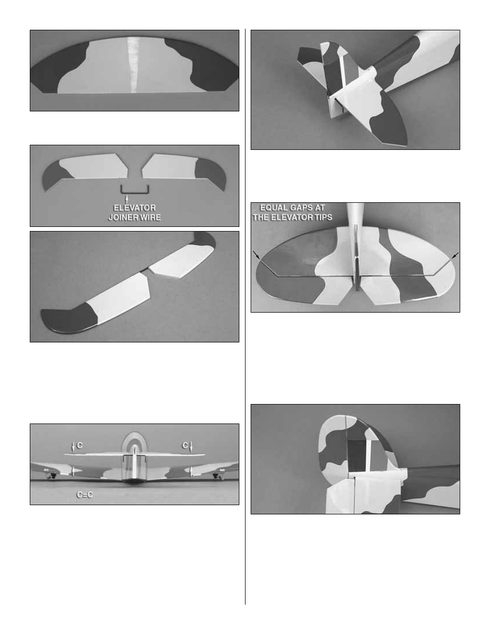
5. Before putting the elevator joiner wire into the stab
slot, trim the covering from the grooves and elevator joiner
wire holes at the TE of the elevator halves. Fit the elevator
joiner wire into the elevators and lay them down on a flat
work surface. Both elevators should lay flat. If not, gently
twist the joiner wire until they do (remove the elevator joiner
wire from the elevator halves before bending).
❏
6. Insert the elevator joiner wire into the back of the stab
slot along with the stab. Stand back several feet and view the
model from the back. Confirm that the stab is aligned
parallel with the wing. If necessary, lightly sand the stab
pocket or add weight to one side of the stab to bring them
parallel. When satisfied, glue the stab in place with epoxy.
For a strong joint, apply epoxy to the inside of the stab
pocket and onto the stab itself. Wipe away any excess epoxy
with alcohol and let the epoxy cure undisturbed. Be sure that
the epoxy does not contact the joiner wire.
❏
7. Fit the vertical fin into the fuse and trace around it onto
the fin. Remove the fin and cut the covering away slightly
beneath the lines you drew (leave the covering on the TE of the
fin in place). Use epoxy to glue the fin in position.
❏
8. Insert a hinge half way into each hinge slot in the stab
and keep them centered with a pin. Coat the ends of the
elevator joiner wire with epoxy. Join the elevator halves to
the stab by first fitting the joiner wire ends into the mating
holes in the elevators, then fitting the CA hinges into place.
Before wicking thin CA glue into the hinges, position the
elevator halves so that the gaps between the stab ends and
the elevator tips are equal.
❏
9. Join the rudder to the fuse and fin with CA hinges.
13