Great Planes Spitfire 25 GP/EP ARF - GPMA1478 User Manual
Page 14
❏
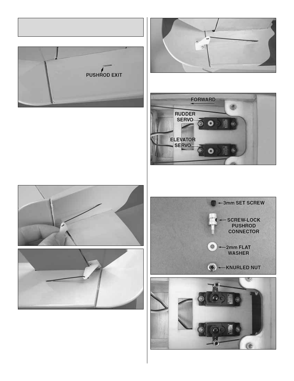
1. Locate and remove the covering from the pushrod
exits on both sides of the fuse beneath the stab.
❏
2. Insert one of the 19-3/4" [502mm] pushrod wires through
the left pushrod exit slot into the fuse. Hook a nylon control horn
onto the Z-bend in the pushrod wire. Align the control horn onto
the underside of the left elevator half and position the holes over
the hinge line at a slight inward angle matching the angle of the
pushrod. When satisfied, mark the locations for the control horn
mounting screws. Drill the holes using a 5/64" [2mm] drill bit and
install the control horn with two 2mm x 15mm machine screws
and a control horn backplate.
❏
3. With the other 19-3/4" [502mm] pushrod, install a control
horn on the right side of the rudder in the same manner.
❏
4. Using the hardware supplied with the servos, install
the elevator and rudder servo into the fuse with the servo
splines facing forward. Be sure to reinforce the servo
mounting screw holes with thin CA.
❏
5. As you did with the ailerons, cut three arms from the
elevator and rudder servo arms. Enlarge the outer hole of each
Install the Elevator & Rudder
Pushrods & Servos
14
- Avistar Elite .46 ARF - GPMA1005 (36 pages)
- Avistar Elite .46 RTF - GPMA1605 (20 pages)
- Big Stik 40 ARF MonoKote - GPMA1220 (24 pages)
- Cessna 182 Skylane 40 ARF - GPMA1228 (28 pages)
- Cherokee GP/EP ARF - GPMA1033 (28 pages)
- Christen Eagle 46 ARF - GPMA1431 (36 pages)
- Cirrus SR22 .46-55 ARF - GPMA1363 (32 pages)
- Citabria EP ARF - GPMA1127 (20 pages)
- Curtis P-6E Hawk EP Biplane ARF - GPMA1164 (24 pages)
- Dirty Birdy .60 ARF - GPMA1975 (44 pages)
- Easy Sport 40 ARF MonoKote - GPMA1036 (24 pages)
- Edge 540T EP ARF - GPMA1572 (24 pages)
- ElectroStik EP ARF - GPMA1574 (20 pages)
- ElectroStik EP RxR - GPMA7500 (16 pages)
- Escapade .61 GP/EP ARF - GPMA1201 (28 pages)
- Escapade EP/GP ARF - GPMA1200 (28 pages)
- Escapade MX 30cc ARF - GPMA1210 (32 pages)
- Escapade MX GP/EP ARF - GPMA1202 (24 pages)
- Evader EDF Sport Jet EP ARF - GPMA1800 (24 pages)
- Extra 300SP EP ARF - GPMA1188 (24 pages)
- Extra 300SP Performance Series ARF - GPMA1022 (28 pages)
- Extra 330SC EP ARF - GPMA1129 (20 pages)
- F1 Rocket Evo GP/EP ARF - GPMA1030 (28 pages)
- F-16 Falcon EDF ARF - GPMA1801 (24 pages)
- F-20 Tigershark Electric Ducted Fan ARF - GPMA1875 (16 pages)
- F-86 Sabre Micro EDF TxR - GPMA1771 (12 pages)
- Factor 3D ARF - GPMA1552 (20 pages)
- Fling ARF - GPMA1060 (16 pages)
- Fling DL ARF - GPMA1070 (16 pages)
- FlyLite EP Slow Flyer ARF - GPMA1107 (24 pages)
- Giant Big Stik ARF - GPMA1224 (32 pages)
- Giant Citabria 30cc/EP ARF - GPMA1435 (44 pages)
- Giant Revolver ARF - GPMA1425 (32 pages)
- Giant Super Sportster ARF - GPMA1044 (32 pages)
- Goldberg Super Chipmunk EP ARF - GPMA1928 (20 pages)
- Kunai 1.4M EP ARF - GPMA1815 (16 pages)
- Lanier RC Stinger II - GPMA1010 (24 pages)
- Matt Chapman Eagle 580 46/EP ARF - GPMA1281 (32 pages)
- Mister Mulligan EP ARF - GPMA1485 (32 pages)
- P-51 Mustang GP/EP ARF - GPMA1205 (24 pages)
- P-51 Mustang Sport Fighter .46 EP ARF - GPMA1208 (28 pages)
- PBY Catalina ARF - GPMA1154 (20 pages)
- Phazer EDF ARF - GPMA1802 (24 pages)
- Pluma 3D Bipe ARF ARF - GPMA1130 (24 pages)
- Proud Bird ARF - GPMA1260 (28 pages)