Great Planes Spitfire 25 GP/EP ARF - GPMA1478 User Manual
Page 10
❏
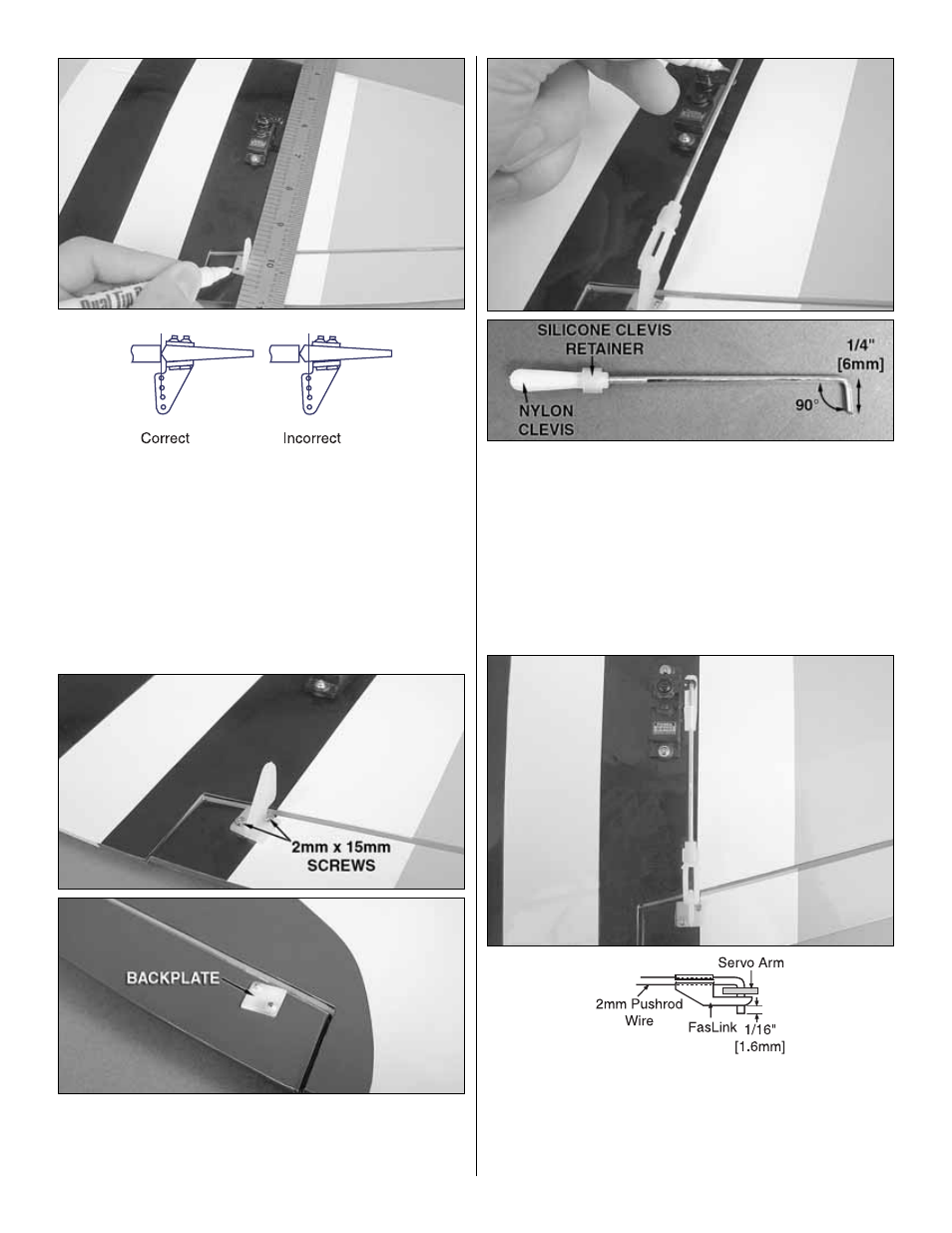
8. Place a control horn onto each aileron in line with the outer
hole of the servo arm. We used a ruler as a straightedge.
Position the horn so that the holes in the horn are centered
above the aileron hinge line. Use a fine, felt-tip pen or a T-pin to
mark the locations of the control horn screws onto the ailerons.
❏
9. Drill holes at your marks through the ailerons using a
5/64" [2mm] drill bit. Install the control horns using 2mm x
15mm machine screws and the control horn backplates. The
ends of the screws can be cut flush with the backplates.
❏
10. Locate a 2mm x 120mm pushrod wire threaded on one
end. Screw a nylon clevis and a silicone clevis retainer onto the
threaded end of the wire 20 full turns. Install the clevis onto the
outer hole of the control horn. (If necessary, enlarge the hole
with a 5/64" [2mm] bit.) Center the servo arm (perpendicular to
the servo case) and center the aileron (use tape or small clamps
to hold it in place). Mark the location where the wire crosses the
outer hole in the servo arm. Bend the wire 90 degrees at this
mark and cut the excess wire 1/4" [6mm] beyond the bend.
Repeat this step for the other pushrod.
❏
11. Enlarge the outer hole in the servo arm with a
Hobbico Servo Horn Drill or a 5/64" [2mm] drill bit. Attach the
clevis to the control horn, slide the silicone clevis retainer
over the clevis and install the 90° bend in the wire into the
servo arm and retain it with a nylon FasLink. Connect the
pushrod for the other wing panel the same way.
10