Great Planes Spitfire 25 GP/EP ARF - GPMA1478 User Manual
Page 18
the fuel tank! The bottom of the tank is 7/8" [22mm] above the
top of the cooling hole cutout. To allow for some error, be sure
that your hole is 5/8" [16mm] or closer to the cooling hole
cutout. If in doubt, remove the tank before drilling your hole.
Drill a hole through the second fuse former inline with the first
(a long drill bit is helpful here). Insert the 1/8" x 9-5/8" [3mm x
245mm] nylon pushrod tube through the holes. Use CA to glue
the tube flush with the front of the firewall.
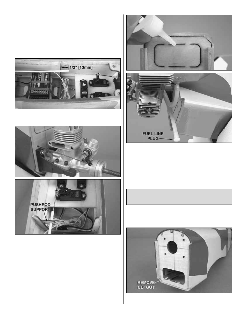
❏
14. Cut off the excess pushrod tube 1/2" [13mm] behind
the third fuse former.
❏
15. Install the .039" x 13-3/4" [1mm x 350mm] throttle
pushrod with Z-bend into the outer pushrod and connect the
Z-bend to your engine throttle arm (you may need to remove
the arm from the carburetor to do this). Install a screw-lock
pushrod connector into the outer hole of the throttle servo
arm and test fit it onto the servo. A pushrod support is
provided and can be glued to the former just in front of the
throttle servo. You may need to sand or cut this part to length
depending on the pushrod position. When satisfied, slide the
support onto the pushrod tube and glue it in place. Tighten
the aft end of the throttle pushrod in the screw-lock pushrod
connector (do not cut off the excess length of pushrod until
you have used your radio system to center the servo and
have made your adjustments to the pushrod length).
❏
16. Run a bead of medium or thick CA glue along the
brushless motor cooling hole cutout lines. Trim the fuel
tubing to length and connect the vent line to the muffler and
the carb line to the fuel inlet on the needle valve. A plastic
fuel line plug has been provided to plug the fill line if you
installed one.
If you have installed a glow engine, skip this section as it only
contains information relevant to installing a brushless motor.
❏
1. Cut the perforations along the cooling hole and remove
the cutout.
Out-runner Motor, Battery
& Radio Installation
18