Great Planes PolyCharge4 - GPMM3015 User Manual
Page 2
WARNING!! Never attempt to care for lithium-polymer
(Li-Po) cells in the same way as other battery types!! It is
very important to have a good understanding of the operating
characteristics of Li-Po batteries—especially their exact rated
voltage and maximum acceptable charge current. Always
read the specifications printed on the label of your Li-Po
battery prior to use. Great Planes will not be held responsible
for any and all incidental damages and bodily harm that may
result from improper use of lithium-polymer batteries with this
charger. Failure to follow the care and handling instructions
can quickly result in severe, permanent damage to the
batteries and its surroundings and even start a FIRE!
Do not mistaken lithium-polymer cells for other lithium-based cell
types (such as lithium-metal, lithium-phosphate, etc.), as other
lithium hybrids have different care and handling characteristics
as well. All “lithium” based batteries types are NOT the same.
It is strongly recommended to use packs which have been
assembled with a built-in charge protection circuit. Such circuits
help to regulate the maximum voltage per cell in the pack to
ensure that that they do not accidentally become overcharged.
The PolyCharge4 charger is designed to detect the proper
voltages for Li-Po batteries, but it is always a good idea to have
a second level of protection on the batteries as well.
IMMEDIATELY remove a Li-Po battery from a model if it is
involved in a crash in any way. Carefully inspect the battery for
even the smallest of dents, cracks, splits, punctures or
damage to the wiring and connectors. CAUTION! Cells may
be hot! DO NOT allow the battery’s internal electrolyte to get
in the eyes or on skin - wash affected areas immediately if
they come in contact with the electrolyte. A Li-Po battery
might not appear to be damaged after a crash, but it could
smolder over a short amount of time and suddenly catch fire
unexpectedly. If in doubt, place the battery in a fire-proof
location indefinitely.
The PolyCharge4 charger only accepts 12 to 15V DC input
power. The charger will not function properly if the input voltage
exceeds this range. Input power could come from a dedicated
AC/DC power supply or automotive type battery. Due to the
larger potential currents when charging high capacity packs, a
12V hobby field battery may not be suitable for all-day usage.
An AC/DC power supply or 12V automotive battery may be
needed in these applications. The power supply chosen must
be able to supply 14A at 12V DC in order to achieve the
maximum potential from the charger. Applying less than 12V
may result in errors indicated by audio alerts as well as flashing
orange LEDs. It is best to use a clean DC source which has a
filtered output to reduce noise, and high quality connections.
INPUT POWER LEAD: The input power lead is located on
top-rear of the charger.
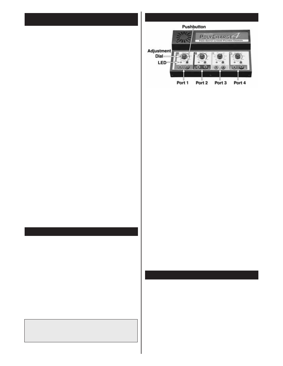
FOUR OUTPUTS: The PolyCharge4 is equipped with four
separate outputs, each being totally independent of the others.
This means that each output should be handled as one single
charger. Each output is rated to deliver a maximum of 30 watts of
power. It is possible that for batteries with high cell counts (3 or 4
cells) and high capacity ratings (over 2.0 amps), the maximum
current actually delivered to the battery might be limited due to
the maximum power rating of the output. This is normal.
There is never a need to be concerned with the setup of one
output in respect to another output. For simplicity, each output is
color coded.The controls and jacks for output 1 are colored in red,
output 2 is is black, output 3 is in yellow, and output 4 is in blue.
Each output consists of (a) one set of banana jacks, (b) a dial
by which to set the rated capacity of the battery to be
charged, (c) a pushbutton, and (d) a tri-colored LED.
FUSE: The over-current protection fuse is located on the left side
of the charger. This charger requires an “ATO” fuse, sometimes
referred to an “auto” or “spade” type fuse. The rating of the fuse is
20A (amps) at 32V (volts). Do NOT replace with a fuse of a higher
current rating than 20A, as it could result in damage to the charger
if an over-current condition occurs! Using a fuse with a rating of
less than 20A might cause the fuse to blow too easily.
FAN: The internal fan is located on the upper-left side of the face
of the charger. The fan helps to keep all internal components
cool during operation. This will help extend the service life of the
charger, as well as allow the charger to function more accurately
and efficiently. The fan will turn on anytime a load is present on
the charger’s output. Do not block the cooling fan and other
vent holes as it could cause an overheating condition to
occur, possibly causing permanent damage to the charger!
1. CONNECTING INPUT POWER: Connect the input power
lead to 12V DC input power. Connect the red, positive (+)
lead to the power source’s positive (+) terminal, and the
black, negative (–) lead to the power source’s negative (–)
terminal. Note that there is no ON/OFF power control
switch. Once connected, the charger is always “on”. Always
disconnect the charger from input power when not in use.
2. CHOOSE AN OUTPUT: Determine which one of the four
outputs which will be used to charge a battery. It is not
necessary to use the outputs in any specific order. One battery
only can be charged on any output, two batteries can be
charged simultaneously on any two outputs, four batteries
simultaneously, etc.
CHARGING A BATTERY PACK
CONTROLS AND BATTERY CONNECTIONS
WARNING! Never accidentally short together the positive
(+) and negative (–) input connections when connected to
12V DC power. Failure to do so could result in permanent
damage to the power source and the charger.
INPUT POWER
IMPORTANT PRECAUTIONS FOR
HANDLING LITHIUM-POLYMER BATTERIES