Futaba 7FGH User Manual
Page 13
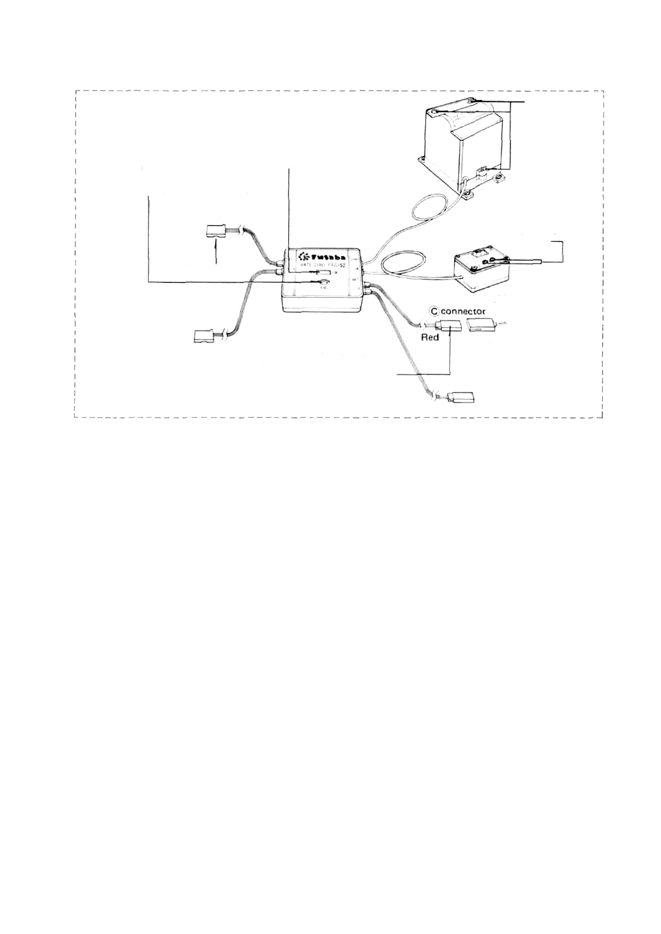
Rate gyro FP-G152
Fig. 21
Connected servo (rud-
der servo for helicopter)
neutral position trim-
mer (This trimmer is
operative even when
the control box power
switch is set to OFF.)
Gyro output polarity switch
Remove
these
screws.
and
remove
the
case.
Gyro body
Connect to receiver
retract or
auxiliary
channel
(for gyro
sensitivity switching)
for Receiver
Control amp
Control box
Gyro output
trimmer
Jumper
connector
for Rudder Servo
Five battery pack 6V connector Motor regulated
power supply. (Insert the jumper connectors when
the power supply is shared with the receiver.)
•Connect the servos and switches firmly as
shown in Fig. 20. Then extend the transmitter
and receiver antennas fully.
•Set the transmitter power switch to ON. then
set the receiver power switch to ON. The servos
stop near the neutral position. Operate the
transmitter sticks and check if the correspond-
ing servos faithfully follow operation of the
sticks.
•After setting the pushrods at the servo horns,
check that the direction of operation of the
transmitter sticks and the direction of opera-
tion of the rudders are the same.
•Operate each servo horn over its entire operat-
ing range and check if the pushrod binds, or is
too loose. Applying unreasonable force to the
servo horn will adversely affect the servo and
quickly drain the batteries. Always make the
operating width of each rudder somewhat larger
than the full stroke (including trim) of the
servo horn. Adjust the servo horns so that
operate smoothly even when the trim lever and
stick lever are operated simultaneouly in the
same direction.
•Be alert for noise.
If engine vibration causes metal parts to touch,
noise will be produced and the receiver and
servos may operate incorrectly. We recommend
the use of noiseless parts.
•When installing the switch, cut a rectangular
hole somewhat larger than the full stroke of the
switch and install the switch so it moves smo-
othly from ON to OFF. When the switch is
mounted inside the fuselage and is turned ON-
OFF with wire, install the switch mount as
described above. Install the switch where it will
not come into direct contact with engine oil,
dust, etc.
•Even though the receiver antenna is long. do
not cut or bundle it.
•The servos, Ni-Cad battery,switches,extension
cords, and crystals of FP-7FGH are the same
as those of the high-quality J Series. The crystals
are extremely precise and are identified by
color (red and green). Use Tx and Rx crystals
of the same color.
•A spare horn is supplied. Use it as needed.
•Wrap the receiver in sponge rubber. Place the
receiver in a plastic bag and wrap a rubber band
around the open end of the bag to waterproof
and dustproof the receiver. Do the same with
the receiver/servo battery.
•Use the rubber bands wrapped around the
receiver to hold the servo and switch leads.
•After mounting is complete, recheck each
part, then make the transmitter antenna as
short as possible, extend the receiver antenna
fully, and operate the set from a distance of
20m to 30m. The movement of each rudder
(servo) should faithfully follow the operation
of each stick of the transmitter.
11