Installation, Mechanical – FloAire INDIRECT FIRED BENT TUBE MODULE User Manual
Page 4
4
INSTALLATION
It is imperative that this unit is installed and operated with the designed airflow, gas, and electrical supply
in accordance with this manual. If there are any questions about any items, please call the service
department at 1-866-784-6900 for warranty and technical support issues.
Mechanical
WARNING: DO NOT RAISE VENTILATOR BY THE INTAKE HOOD, BLOWER OR
MOTOR SHAFT, OR BEARINGS – USE LIFTING LUGS PROVIDED OR A SLING
Site Preparation
1. Provide clearance around installation site to safely rig and
lift equipment into its final position. Supports must
adequately support equipment. Refer to manufacturer’s
estimated weights.
2. Consider general service and installation space when
locating unit.
3. Locate unit close to the space it will serve to reduce long,
twisted duct runs.
4. Do not allow air intake to face prevailing winds. Support
unit above ground or at roof level high enough to prevent
precipitation from being drawn into its inlet. The inlet must
also be located at least 10 feet away from any exhaust
vents. The heater inlet shall be located in accordance
with the applicable building code provisions for ventilation
air.
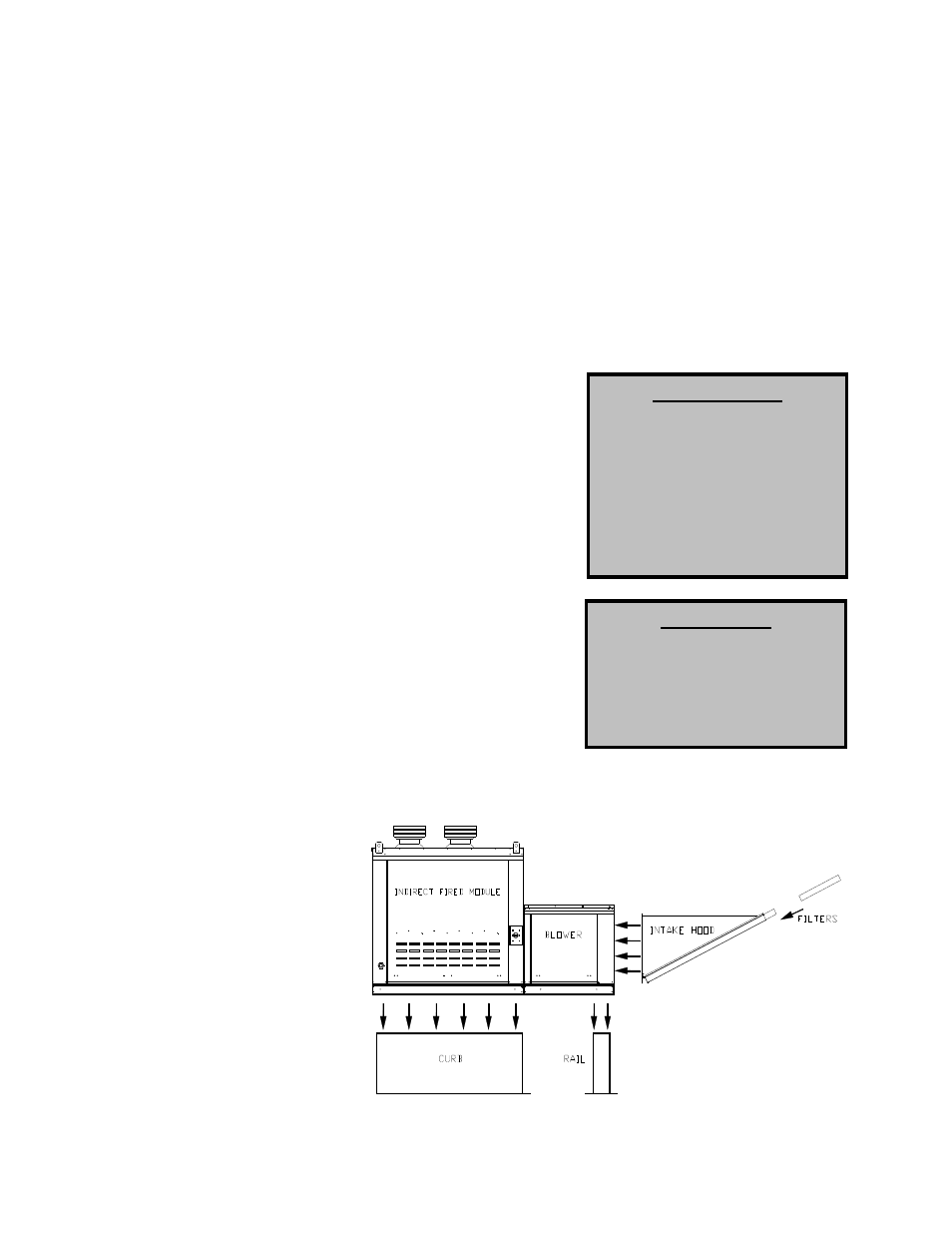
Assembly
Intakes and curbs are shipped unassembled to heater module.
Upon unit arrival, use the following procedure to assemble the
intake to the heater.
1. Apply silicone or weather-proof gasket on the back side of
the flanges of the intake hood or v-bank intake.
2. Screw the flanges of the intake hood or v-bank to the unit with the supplied sheet metal screws.
Place caulk on the outside
of the screws to prevent
water leaks. If the unit is a
modular unit with a v-bank
or
evaporative
cooler
section, the v-bank or
evaporative cooler will bolt
to the heater with the bolts
provided.
Curb and Ductwork
This fan was specified for a
specific CFM and static pressure.
The ductwork attached to this unit
will significantly affect the airflow
performance. Flexible ductwork
CLEARANCES
The top, back, and front
surfaces of this heater may not
be installed less than 6” from
combustible materials. The
heater base may be installed
on
combustible
surfaces.
Allow 24” minimum service
clearance on both sides of this
heater.
IMPORTANT
To prevent premature heat
exchanger
failure,
do
not
locate any gas fired unit in
areas
where
chlorinated,
halogenated, or acid vapors
are present in the atmosphere.