Sequence of operation – FloAire INDIRECT FIRED BENT TUBE MODULE User Manual
Page 23
23
FVFAB
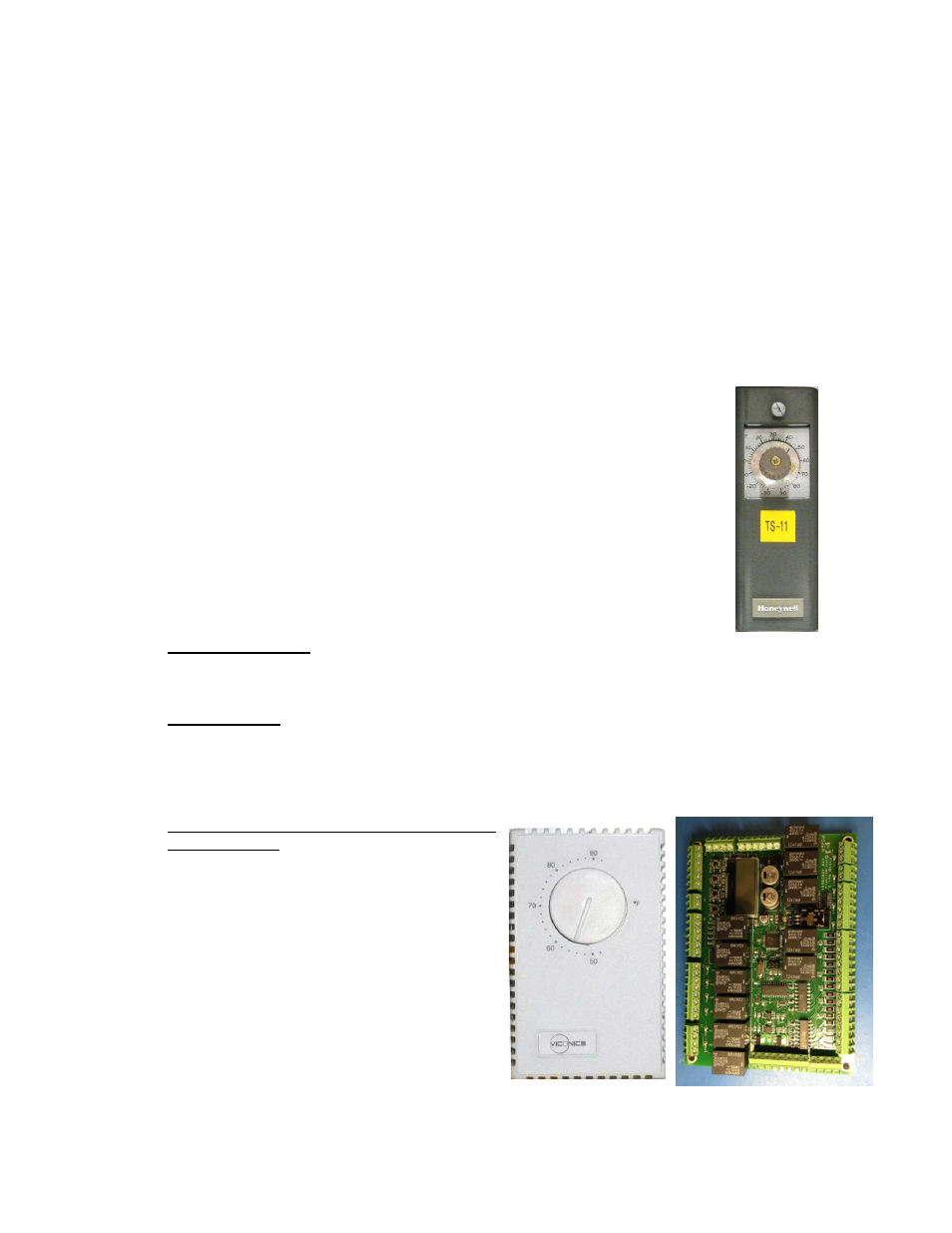
Temperature
Selector Dial
Intake Air
Thermostat
Sequence of Operation
The Indirect-fired heater is most easily understood when broken down into smaller individual systems.
There are two main systems; a make-up air fan and a heater. The make-up air fan consists of a heavy-
duty blower and motor. The heater may be further broken down into two control systems, the Modulating
Gas System (MGS) and the Flame Safety Control (FSC). The burner mixes air with the gas (Natural or
Propane) which heats a heat exchanger which heats the air. There are between one and four furnaces in
each heater depending on the total required heating output capacity for the application. Included in every
unit is at least one modulating furnace, located furthest downstream, closest to the discharge of the
heating module. The modulating furnace(s) and additional On/Off furnaces (if used) are controlled using
vernier-type modulation methods resulting in fully linear heating output over the entire gas-firing range.
Modulating Gas System
The first system, the Modulating Gas System, consists of an Intake Air Thermostat,
a Temperature Selector Dial, a Functional Vernier Functional Auto Balancing
Module (FVFAB), a Discharge Air Sensor (only on discharge temp control option), and a
modulating gas valve(s). The Intake Air Thermostat is only used to give a call for heat
signal to the Flame Safety Controller. It is important to understand that this intake air
thermostat is only used for this purpose and does not control the discharge/space
temperature in which the module tries to maintain. For Kitchen MUA heating
applications, the dial setting on the Intake Air Thermostat should be set at 45 °F,
whereas the Temperature Selector Dial should be set at 55 °F. For all other
applications, the dial settings should be set appropriately based on the end-users
preferences and on-site conditions.
There are 3 different options for controlling the gas firing output of these units. These
include Discharge Temperature Control, Space Temperature Control, and Building
Automation Control. Refer to page 24 for how to configure for each type of control:
1. Discharge Control: When wired for discharge control, the thermostat utilizes a discharge air
sensor in the unit and heats the incoming air to the selected setting on the Temperature Selector
Dial or programmable stat by sending signal voltage to the FVFAB.
2. Space Control: When the space control option has been selected, the Temperature Selector
Dial or programmable stat is mounted in the space, sensing the temperature in the room with use
of
an internal sensor. The discharge sensor in
the unit is not used and the stat sends a signal
voltage directly to the FVFAB.
3. Building Automation Control/Direct Digital
Control (DDC): Use of the Temperature
Selector Dial is completely eliminated and a 0-
10vdc or 0-20mA signal is sent to the FVFAB
from the building control system to regulate the
heating output of the unit.
In all cases, the FVFAB controls the amount of
gas to the burner based on the signal from the
temperature control components. When the
modulating gas valve is all the way open and
achieving the maximum BTUs and temperature
rise of the unit, it is called “high fire”.