FloAire INDIRECT FIRED BENT TUBE MODULE User Manual
Page 16
16
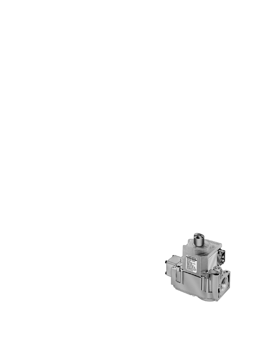
Honeywell ON/OFF Gas Valve
Forced High Fire Light-Off (Modulating Stages)
1. Restart the fan and check the gas supply pressure at the inlet gas tap upstream of all electronic
valves. The inlet pressure should be 7 in. - 14 in. w.c. on natural gas and 11 in. – 14 in. w.c.
on propane gas. If the inlet pressure is too high, install an additional pressure regulator external
to the unit.
2. Open the field installed manual gas shut-off valve and the manual main gas valve on the
combination gas control valve.
3. Check the inlets to all of the firing tubes on the furnace and ensure that they are all clear of
foreign debris and line up properly with each nozzle of the gas manifold.
4. Configuring the FVFAB component for low fire by selecting “menu”, “test mode” and then “low
fire”. Allow the furnace to light (Note: There is a 1 minute standard power-vent flue pre-purge
time prior to the unit attempting to light). If the furnace does not light, purge the gas train and gas
manifold.
5. Upon successfully sensing flame at the upper most firing tube, the unit will fire at full high fire for a
period of 17 seconds. At the end of this timing sequence, it will modulate down to low fire in
accordance with the FVFAB test mode.
6.
Check the characteristics of the flames in every firing tube of the furnace. Non-existence of or a
lazy flame can be caused by low gas pressure, a dirty nozzle orifice, or clogged section of
exhaust flue. To take the FVFAB out of low fire test mode, press any key.
High-Fire and Low-Fire Burner Adjustment
1. After it has been verified that the furnace is lighting off properly, the manifold gas pressure should
be adjusted to jobsite conditions. The gas pressure regulator (integral to the On/Off gas control)
is adjusted at the factory for average gas conditions. It is important that the gas be supplied to
the furnace in accordance with the input rating on the rating plate.
2.
(Skip this step and continue with step # 3 if unit contains only modulating furnaces.)
If there are
additional ON/OFF furnaces in the heater, it must be verified that they are all running at high-fire
manifold pressure before setting high and low fire on the modulating stage. Reference “Gas
Pressure Adjustment Reference Information” in this manual for an overview of proper pressure
settings of all furnaces and a visual representation of the layout of the modulating and ON/OFF
Furnaces. All ON/OFF furnaces must be running in full fire while setting high and low fire on the
modulating gas valve. To do this, the entire unit must be locked into high fire mode. This is
achieved by configuring the heat controller FVFAB by
going to “menu”, “test mode” and then “high fire”. An
alternative method is to disconnect one of the wire
leads to the discharge air sensor, or if the unit is set up
for space temperature control, momentarily configure
the unit to discharge temp control and lock the unit into
high fire mode by changing the dipswitch settings
inside of the remote-mounted, white Viconics
temperature selector Dial/Thermostat in the tempered
space. Refer to the “Modulating Furnace Thermostat
Dipswitch Settings” section of this manual for proper
dip-switch settings. If the Unit is set up for BAS
(Building Automation Control), lock the unit into high
fire by configuring the heat controller FVFAB by going
to “menu”, “test mode” and then “high fire” or
alternatively, sending the unit a constant 10Vdc or
20mA signal. With all burners lit, set the manifold gas
pressure on the non-modulating stages using the
adjustment screw on the ON/OFF Gas Valve. Non-modulating furnaces can be easily identified
as the ones with only a single ON/OFF gas valve on their gas train. Read the manifold gas
pressure off of the 0-10” w.c. pressure indicator gauge on each of these non-modulating stages.