Assemble engine pod assembly (continued), Assemble fuselage tube, Glider adjustments – Estes 2190 – Cosmos Mariner User Manual
Page 3: Balance glider, Glide test
ALIGN
COMPLETED
ENGINE POD TUBE
ASSEMBLY
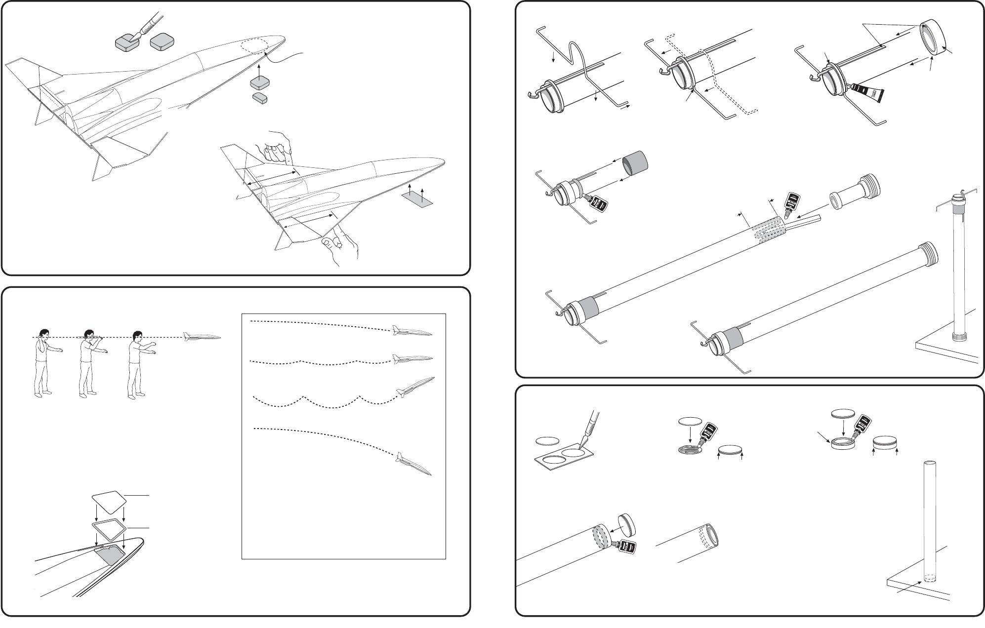
I. Align wire form as shown, tips forward. Loop goes over tube.
Press wire form rearward until it fits into notches in the plastic
pod end ring.
J. Align notch in plastic pod ring with engine hook. Apply
plastic cement around front edge of the plastic pod
end ring. Slide plastic pod ring down tube, making
sure the wire form is trapped between the two rings.
Let dry. Note: Wipe off any excess cement.
K. Apply a ring of glue around tube
ahead of the plastic pod ring.
Slide the black engine hook
retainer ring rearward and under
the ring until tight against ring.
Let dry.
L. Use scrap balsa to smear
glue 1-1/2"
(3.8 cm)
inside
of tube. Insert engine pod
weight assembly into
tube, flush to end.
page 3
page 10
2.
ASSEMBLE ENGINE POD ASSEMBLY (continued)
TIPS
FORWARD
NOTCHES
CUT ONE CLAY
WEIGHT IN HALF
1-1/2"
(3.8 cm)
3.
ASSEMBLE FUSELAGE TUBE
A. Carefully remove discs from card
using a modeling knife. Sand
edges smooth to remove any nibs.
B. Apply glue to top of one disc.
Press both discs together,
align evenly. Let dry.
C. Apply glue to bulkhead ring
and attach discs. Wipe off
any excess glue. Let dry.
D. Apply a ring of glue just inside end of fuselage
tube. Insert disc side of bulkhead assembly into
tube, flush with end.
EVEN
EVEN
BULKHEAD
RING
BULKHEAD END
NOTE: STAND
UPRIGHT UNTIL
COMPLETELY
DRY!
GLIDER ADJUSTMENTS:
If glider dives, remove clay weight from cavity.
If glider stalls, add clay weight to cavity.
If glider turns too sharply, make sure it is balanced
span wise (from side to side). If it is not, add
weight, in small amounts, to the light wing tip until
nearly balanced.
The glider should perform a large, gliding circle
during descent.
13.
BALANCE GLIDER
B. Add or subtract clay weight until
glider balances between 7-1/8" to
7-3/8"
(18.1 to 18.7 cm)
from rear of
glider. Hold clay in place
temporarily with masking tape.
14.
GLIDE TEST
A. Insert 1-1/2 squares of clay
into cavity located on
bottom front of fuselage.
7-1/8" to 7-3/8"
(18.1 to 18.7 cm)
HOLD CLAY
TEMPORARILY
WITH MASKING
TAPE
A. With engine pod removed from glider, aim for a spot about
50 feet
(15 m)
away and toss glider straight out at eye level.
B. Observe glide carefully. Make adjustments a little at a time
until you are satisfied with the glide.
NOTE: Test the glider only on soft, grassy surfaces like a sports field
or lawn so that you don't damage your model.
DOOR
DOUBLE-SIDED
DOOR TAPE
Once you are satisfied with the glide, remove the tape that holds the
clay in place, being careful not to dislodge any of the clay. Remove
backing from double-sided door tape and apply tape to plastic door.
Remove other side of backing and attach door to fuselage, pressing
door firmly onto fuselage and securing clay weight in place.
CORRECT FLIGHT-
SLOW LOSS OF
ALTITUDE
LIGHT STALL-OK
HEAVY STALL-
CORRECT IT
DIVE-DON'T LET THIS
HAPPEN TO YOU
PLASTIC
POD
RING
FLAT
SIDE
FRONT
REAR
PLASTIC
POD END
RING
E. Stand upright on bulkhead
end until completely dry.
Do not lay on its side.
COMPLETED
FUSELAGE
ASSEMBLY