Prepare engine, Assemble engine mount, Attach centering rings – Estes 2188 – Canadian Arrow User Manual
Page 2: Finishing your rocket, Prepare parachute for flight, Paint mask
3/8”
(9.5 mm)
1.
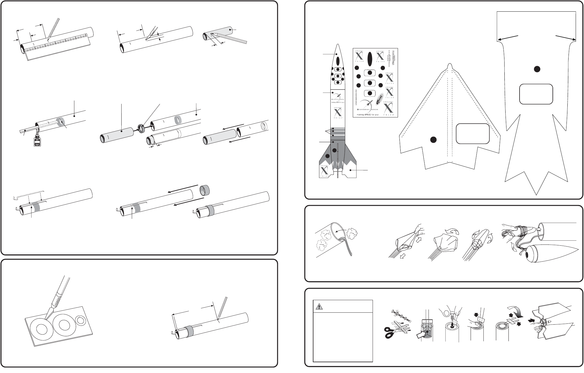
ASSEMBLE ENGINE MOUNT
A.
Measure and mark Engine Mount Tube.
B.
Cut 1/8” (3 mm) slit at 2 3/8” (6 cm)
mark.
G.
Apply glue around tube just ahead of
the 1” (25 mm) mark. Insert Engine
Hook into slit, as shown.
H.
Slide Engine Hook Retainer Ring onto Engine Mount Tube up to 1” (25 mm)
mark. Let dry.
1”
(25 mm)
MARK
C.
Mark Yellow Spacer Tool 3/8”
(9.5 mm) from end.
D.
Use scrap balsa to smear glue 2 3/8” (6 cm)
inside Engine Mount Tube.
YELLOW SPACER
TOOL
REAR
1/8”
(3 m
m)
E.
Use Engine Spacer Tool to push Engine
Block into Engine Mount Tube up to mark.
2 3/8”
(6 cm)
GLUE INSIDE
GLUE
REAR
2 3/8”
(6 cm)
FRONT
ENGINE MOUNT TUBE
SCRAP
BALSA
2.
ATTACH CENTERING RINGS
FRONT
1”
(25 mm)
2 3/8”
(6 cm)
INCH
ES
1
2
3
4
5
6
A.
Using a modeling knife, carefully remove
rings from Centering Ring card.
B.
Mark Engine Mount Tube at 1/8” (3 mm) and
5 7/8” (14.9 cm) from rear.
5 7/8”
(14.9 cm)
REAR
FRONT
1/8”
(3 mm)
2
7
B.
Spike Parachute.
C.
Fold.
D.
Roll.
E.
Wrap lines loosely. Insert ‘Chute, Shock
Cord and Nose Cone into Body Tube.
NOTE: Only
Estes Wadding
(#302274)
Recommended.
PREPARE ENGINE
11.
FINISHING YOUR ROCKET
A. First spray rocket with white primer. Do
not get primer or paint inside Engine
Mount. Let dry and sand. Repeat until
rocket is smooth. FOLLOW THE PAINT
SCHEME ON THE PACKAGE.
PREPARE PARACHUTE FOR FLIGHT
A.
Insert 6-8 squares of loosely
crumpled recovery wadding into
rocket.
A.
Separate
Igniter and
Plug.
B.
Tip must
touch
propellant!
C.
D.
E.
F.
Insert Engine
To avoid serious injury, read
instructions & NAR Safety Code
included with engines.
PREPARE YOUR ENGINE
ONLY WHEN YOU ARE
OUTSIDE AT THE LAUNCH
SITE PREPARING TO
LAUNCH!
If you do not use your prepared
engine, remove the igniter before
storing your engine.
WARNING: FLAMMABLE
C. When paint is dry, peel decals one at a time
from backing sheet and apply where shown.
Rub down to remove bubbles.
OPTIONAL: Spray a clear coat on entire
rocket after paint dries and after decal
placement.
WHITE
WHITE
WHITE
RED
ALIGN TO TOP OF FIN
ALIGN
WITH FIN-TUBE JOINT
ALIGN
WITH FIN-TUBE JOINT
BOTTOM
FOLD O
VER FIN LEADING EDGE
FOLD ON
T
O
BOD
Y
FO
LD O
N T
O
B
OD
Y
BOTTOM
A
A
B
WHITE
LET DRY.
F.
Remove Spacer Tool immediately.
3/8”
(9.5 mm)
ENGINE MOUNT
TUBE
GREEN ENGINE
BLOCK
YELLOW SPACER
TOOL
1”
(25 mm)
MARK
COMPLETED ASSEMBLY
B. Trace or photocopy Paint Masks A and
B onto separate sheets of paper. Do
not cut out originals.
TRACE SHAPE
ON SEPARATE
PAPER AND
MAKE 4 MASKS
TRACE SHAPE
ON SEPARATE
PAPER AND
MAKE 4 MASKS
PAINT
MASK
TOP
TOP
B
PAINT
MASK