Tx rx – DVIGear DVI-7525 User Manual
Page 10
-8-
For RS-232, use serial cables and the supplied
3-pin phoenix connectors to connect a controller
unit (e.g. touch panel) and serial controlled device
(e.g. projector) to the RS-232 ports on the Tx and
Rx. Please see the drawing of the female phoenix
connector on the unit for RS-232 pin definitions.
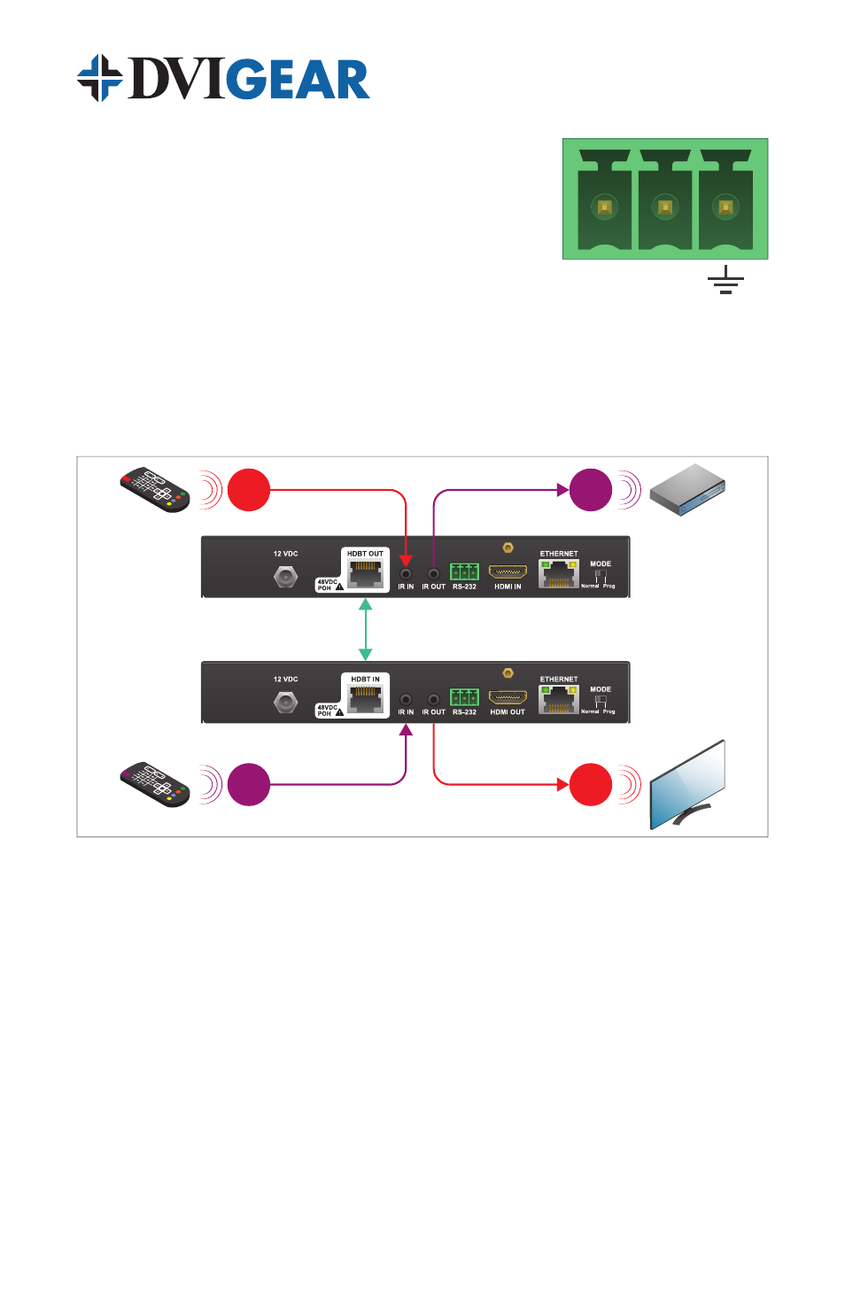
These extenders support bidirectional IR via two
separate IR signals. An IR signal may be extended
over the CAT-X cable from Tx Unit to the Rx Unit by doing the following. Connect
the supplied IR Receiver to the IR IN port of the Tx Unit. Next, connect the
supplied IR Transmitter to the IR OUT port on the Rx Unit. To send an IR signal in
the opposite direction (i.e. from Rx to Tx), simply connect the IR Receiver to the IR
IN on the Rx Unit and the IR Transmitter to the IR OUT on the Tx Unit.
The DVI-7525 extender pair supports extension of 100BaseT Ethernet over the
CAT-X cable. Take care to only connect compatible devices to the ports marked
“Ethernet” on the rear of the DVI-7525 extender pair. Connecting Ethernet devices
to the HDBaseT ports or connecting HDBaseT devices to the Ethernet ports may
result in damage. Please see the warning at the bottom of page 6.
4.2 Power Connections and POH Remote Power
The DVI-7520 and DVI-7525 are fully compliant with the Power over HDBaseT
(POH) component of the HDBaseT standard. During POH operation, the
transmitter unit functions as a PSE (Power Sourcing Equipment) device that
sends 48 VDC power over the CAT-X cable to the receiver unit, which acts as
a PD (Powered Device). This feature eliminates the need for an external power
supply at the receiver. To maintain compatibility and interoperability with other
POH system components, these products use a sophisticated handshake
feature that prevents power exchange with non-standard (incompatible) devices.
Receiver
Transmitter
HDBaseT CAT-X
connection
IR RX
IR TX
IR TX
IR RX
Tx
Rx