Dynaflite DYFA3045 User Manual
Page 27
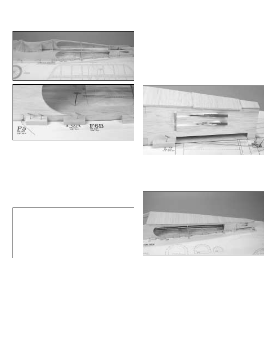
Refer to these photos for the following
four steps.
❏
7. Pin the fuse top back to the plan with Plan
Protector underneath. Without using any glue,
join both fuselage sides to the fuse top. Use
balsa sticks T-pinned to the plan to hold the fuse
sides tightly to the fuse top.
❏
8. Add die-cut 1/8" [3.2mm] plywood formers
F3 through F9 to the assembly.
❏
9. Cut the four 3/16" x 36" [4.8 x 915mm]
pushrod tubes to a length of 30-1/2" [775mm].
Save one of the remaining 5-1/2" [140mm]
pieces for the throttle pushrod tube. Roughen
the outside of the tubes with coarse sandpaper
so glue will adhere, then slide them through the
holes in the formers as shown on the plan.
(Some of the following photos may only show
three tubes.)
❏
10. Making certain all the parts fit correctly
and that the fuse top is fully contacting the
plan, use medium CA to carefully glue all the
formers to the fuse sides and fuse top. Glue the
fuselage sides to the fuse top from F3 aft. Do
not glue the fuselage sides to the fuselage top
from F3 forward until instructed to do so. When
gluing the fuse sides to the fuse top aft of
former F9, use a builder’s square to hold the
fuselage sides vertical.
❏
11. Use medium CA to glue the pushrod tubes
to the formers. Glue the aft end of the pushrods
to the stab saddles and fill the slot with 30-
minute epoxy mixed with microballoons.
❏
12. Sheet the bottom of the fuselage from F5
aft using the 1/8" x 3" x 36" [3.2 x 75 x 915mm]
balsa sheet.
❏
13. Remove the fuselage from the building
board. Sand the bottom sheeting and the
pushrod tubes even with the fuselage sides.
❏
14. Place the bottom wing in the wing saddle.
Taking accurate measurements, mark the center
Note: Though there are two
elevator
pushrods and one rudder pushrod, four
pushrod
tubes
are
installed
in
the
fuselage–the unused pushrod tube is for the
receiver antenna. The rudder servo will be
mounted to the side of the fuselage opposite
the throttle servo.
27