Gas manifold pressure (48 series units only), Unit voltage, Leak test and dehydration – Carrier NP034-074 User Manual
Page 39: Evaporator-fan belts, pulleys, and sheaves
If oil charge is above sight glass, do not remove any oil
until the compressor crankcase heater has been on for at least
24 hours. When additional oil or a complete charge is needed,
use only Carrier-approved compressor oil.
Approved oils:
Texaco, Inc. ................................................. Capella WF-32
Shrieve Chemical Co. ....................... Zerol 150 (Synthetic)
Witco Co. .......................................................... Suniso 3GS
Do not reuse drained oil and do not use any oil that has
been exposed to the atmosphere.
Gas Manifold Pressure (48 Series Units Only)
—
Check pressure to ensure it matches the pressure stamped
on the valve body. See Gas Valve Adjustment section on
page 50 for more details.
Unit Voltage —
Be sure power source agrees with the
unit nameplate rating.
Leak Test and Dehydration —
Be sure there are no
refrigerant leaks. All units are shipped with a complete op-
erating charge of R-22 (Tables 1A and 1B) and should be
under sufficient pressure for leak testing after installation. If
there is no system pressure, add refrigerant until a pressure
is observed and then check for leaks. After leaks are re-
paired, remove and recover refrigerant from the system. For
leak testing procedures, see Carrier Standard Service Tech-
niques, Refrigerants section. Do not use the system com-
pressors to remove refrigerant from the system.
Evaporator-Fan Belts, Pulleys, and Sheaves —
Belts, pulleys, and sheaves are factory installed. All pulleys
are nonadjustable.
See Tables 1A and 1B for fan shaft center distance ranges
and shaft sizes when making selections for field-supplied drives.
See Tables 9A and 9B for a complete listing of field-
supplied pulleys and belt connections.
Check the lubrication of fan and motor bearings. Bearings
are shipped full of grease for corrosion protection and may
run warm temporarily on start-up until the excess grease has
discharged. Check bearing setscrews for tightness. Also check
the tightness of the setscrews on the fan wheel and on the
fan and motor sheaves. Check fan shaft bearing mountings
for tightness.
Recheck sheave alignment and belt tension. See Adjust-
ments section on page 46 for instructions.
Hand-turn the fan to make sure the fan wheel does not rub
on the fan housing. The fan shaft and motor shaft must be
free wheeling before power is applied to the unit.
Following the necessary electrical checks, check for fan
vibration. If excessive vibration occurs, check for:
• drive misalignment
• mismatched belts
• wheel or sheaves loose on shaft
• loose bearings
• loose mounting bolts
• motor out of balance
• sheaves eccentric or out of balance
• wheel out of balance (replace if necessary)
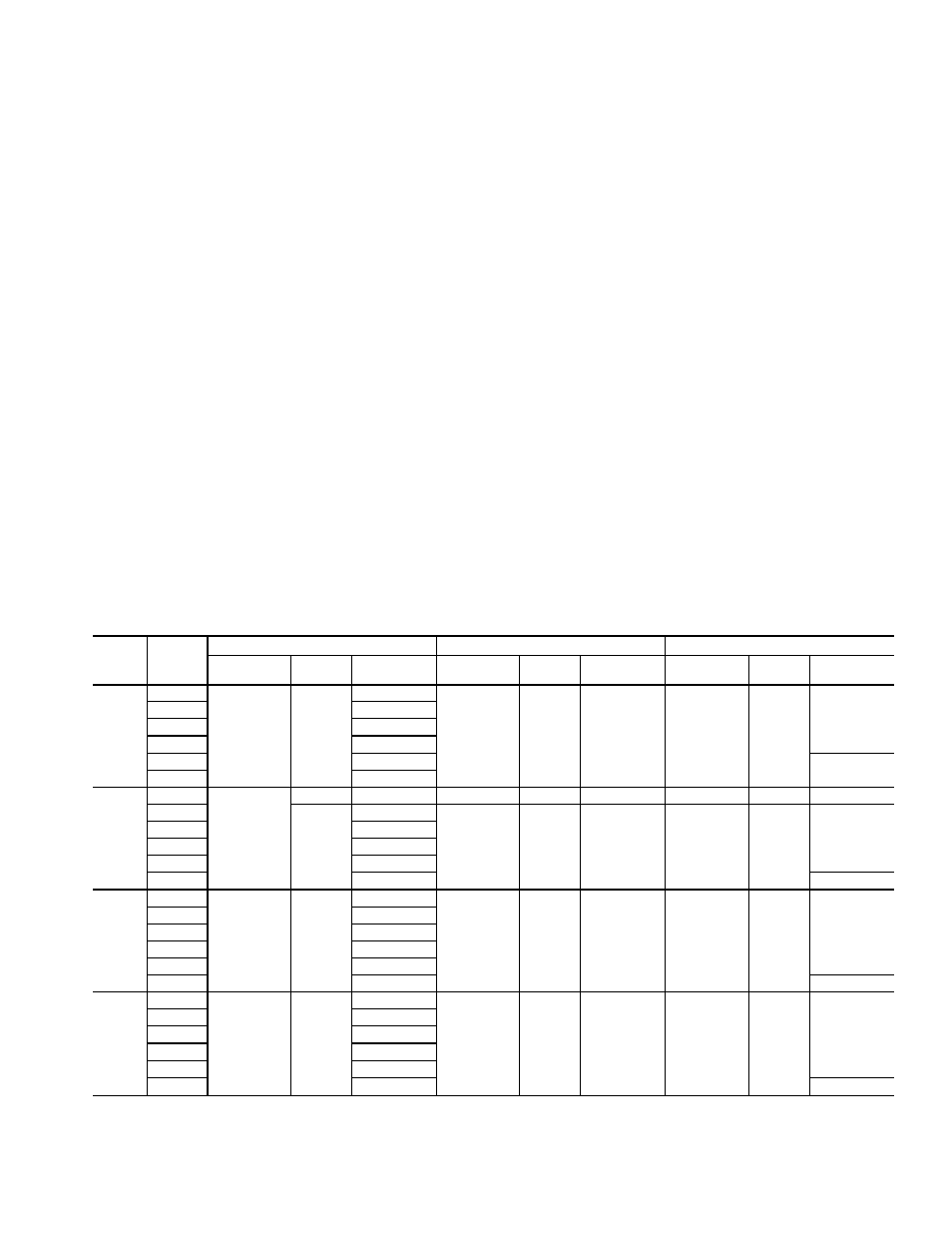
Table 9A — Field-Supplied Evaporator-Fan Pulley Data, 034,044 Units
IFM
Hp
IFM
RPM
MOTOR PULLEY
BLOWER PULLEY
BELTS
No.
Grooves
Type
Size (in.)
No.
Grooves
Type
Size (in.)
Quantity
Type
Size (in.)
7
1
⁄
2
435
2
BK
3.4
2
B5V
13.6
2
BX
61.8
500
3.9
590
4.6
650
5.1
720
5.6
64.8
820
6.4
10
500
2
BK
3.9
2
B5V
13.6
2
BX
61.8
550
B5V
4.3
2
B5V
13.7
2
5VX
63.0
575
4.5
650
5.1
730
5.7
830
6.5
66.0
15
550
2
B5V
4.3
2
B5V
13.7
2
5VX
63.0
625
4.9
675
5.3
730
5.7
800
6.3
880
6.7
66.0
20
575
2
B5V
4.5
2
B5V
13.7
2
5VX
63.0
625
4.9
700
5.5
750
5.5
830
6.5
880
6.9
66.0
IFM — Indoor (Evaporator) Fan Motor
39