Carrier NP034-074 User Manual
Page 17
Field Wire Routing
UNIT SIZES 034 AND 044 — Field wiring can be brought
into the unit through the basepan and roof curb or through
the corner post in the side of the unit next to the control box.
A 3-1/2 in. NPT coupling for field power and a 3/4-in.
NPT coupling for 24 v control wiring are provided in the
basepan. There are two 4-5/8 in. knockouts in the corner post
for field power wiring.
If field power wiring is brought through the roof curb, route
wiring out through one of the 4-5/8 in. knockouts to the field-
supplied disconnect and then back into the unit through the
other knockout. See Fig. 16 for recommended disconnect
location.
If power wiring is brought through the side of the unit,
route wiring from field-supplied disconnect through top
4-5/8 in. knockouts into unit.
If control wiring is to be brought in through the side of the
unit, a 7/8-in. diameter hole must be drilled in the corner
post next to the control box.
UNIT SIZES 054-074 — Field wiring is brought into the
unit through the bottom of the control box. Wiring can be
brought through the roof curb through field-supplied water-
tight connections. See Fig. 17.
A 4-5/32 in. hole for field power wiring and a 7/8-in. hole
for 24 v control wiring are provided in the bottom of the
control box. Field-supplied couplings must be used when rout-
ing wiring into the control box.
See Fig. 17 for recommended disconnect location.
Field Electrical Connections
IMPORTANT: The 48/50DK,DY,NB,NP units gener-
ate, use, and can radiate radio frequency energy. If units
are not installed and used in accordance with these
instructions, they may cause radio interference. They
have been tested and found to comply with limits of a
Class A computing device as defined by FCC (Federal
Communications Commission) regulations, Subpart J
of Part 15, which are designed to provide reasonable
protection against such interference when operated in
a commercial environment.
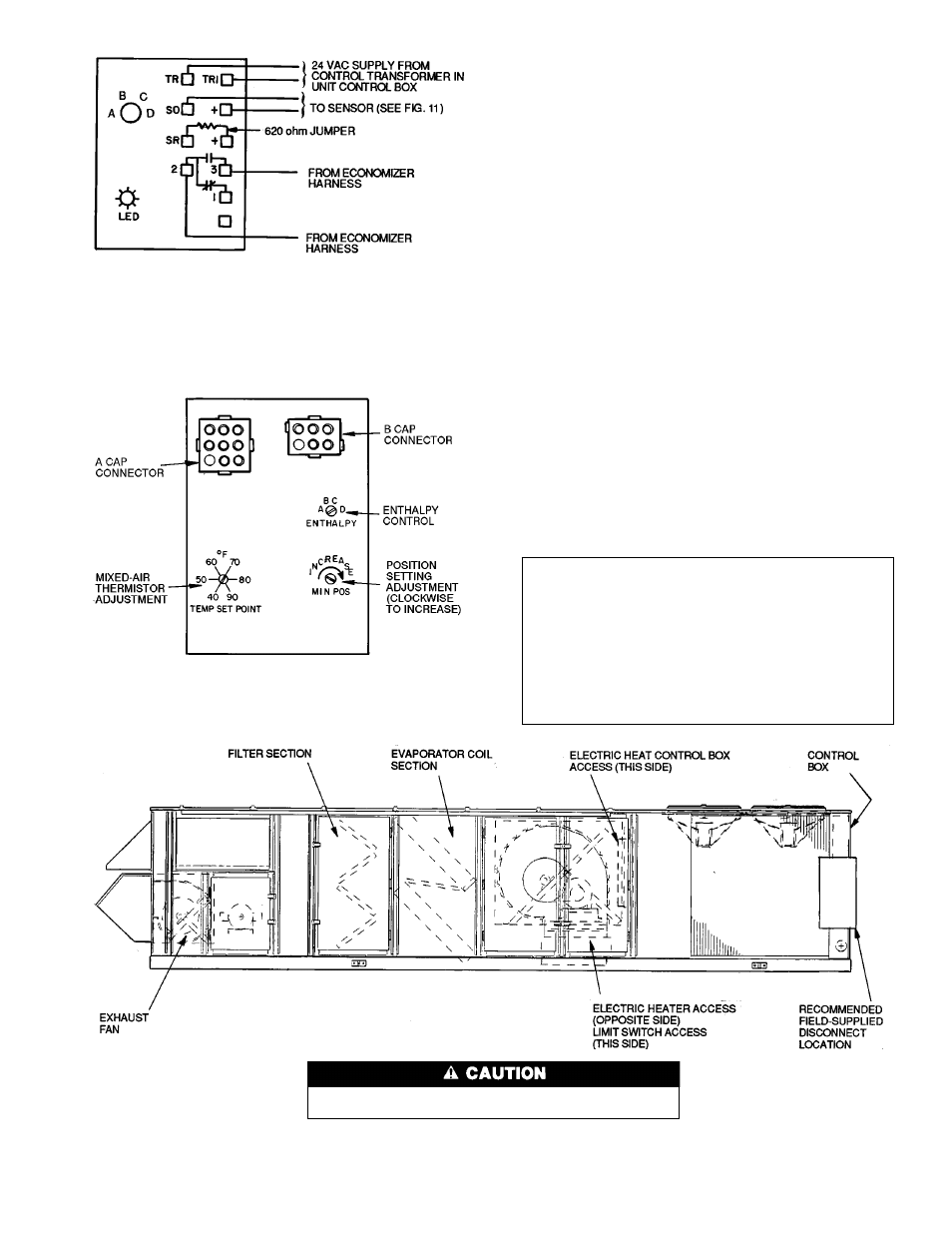
NOTES:
1. Switches shown in high enthalpy state. Terminals 2 and 3 close
on enthalpy decrease.
2. When standard economizer is used with accessory differential en-
thalpy sensor, set enthalpy control to ‘‘D’’ setting.
Fig. 14 — Wiring Connections for Solid-State
Enthalpy Sensor (HH57AC077)
Fig. 15 — Mixed-Air Thermistor and Economizer
Position Setting Adjustments
(Top of Economizer Motor)
Use care when drilling into corner post to avoid damage to con-
denser coil.
Fig. 16 — Disconnect Location, 034 and 044 Units
(50 Series Vertical Discharge Unit Shown)
17