Strap is used to hold the module in place – DLE 35RA User Manual
Page 6
6
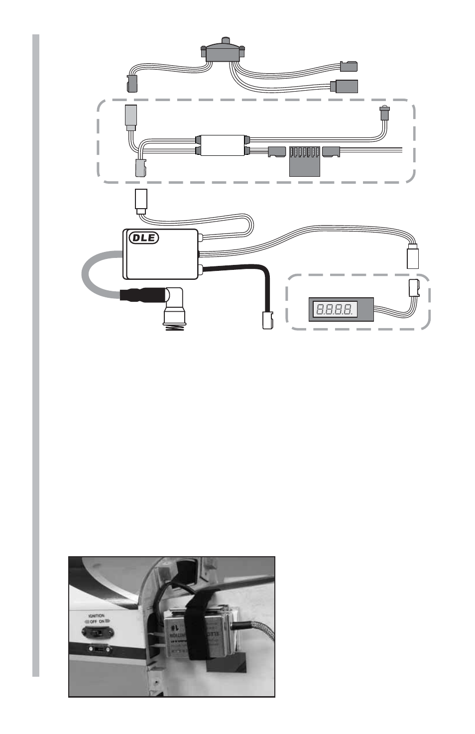
Ignition Wire
(To Spark Plug)
Ignition Control Switch Wire
(To On/Off Switch)
Pick-Up
Sensor Wire
(To Sensor
On Engine)
Tachometer Lead/
RPM Signal Output
ELECTRONIC IGNITION
SYSTEM
Battery Lead
Charge Lead
Switch
(Not included)
Tachometer
(Not included)
DLEG5525
OPTO Gas Engine Kill Switch
(DLEG9205, not included)
OPTIONAL
OPTIONAL
Ignition
Battery Lead
Ignition
Rx Batt
Lead
Rx
LED
KILL
SWITCH
4. Connect the ignition module battery to the on/off switch. Any
4.8 – 8.4V, 1000mAh and above capacity battery will work well for
this. Use heat shrink tubing to secure this connection. Optional:
Install the TX activated gas engine kill switch (DLEG9205) between
the manual on/off switch and the ignition as shown above. This is
especially important during the starting sequence as it requires the
manual on/off switch to be in the ON position before ignition can
occur. The kill switch LED should be installed on the exterior of the
aircraft so that it’s visible from the front of the aircraft. This is to
ensure that the person starting the engine is aware that the ignition
is armed. If properly installed as shown above, an illuminated red
LED indicates that that the ignition is armed.
5. Install the ignition on/off switch on the aircraft so that it is
easily accessible.
6. Install the ignition module
and battery securely in the
airplane forward area. It is
recommended that a thin
piece of foam rubber is
placed between the module
and the mounting surface
and that Velcro
®
strap is used
to hold the module in place.