D.A.S. Audio CSA Series User Manual
Page 21
3
INTRODUCTION
General
Thank you for purchasing a D.A.S. power
amplifier. It has been built with the most advanced
modular technology, and has been designed
through the use of computer-aided design for both
the electronic and mechanical parts.
Features
?
?
?
?
?
?
?
?
?
?
?
?
?
?
?
?
Dual balanced XLR and Terminal Block input
connectors.
Output terminal connections.
Variable speed back-to-front fan cooling.
Front located volume controls.
Overload and short-circuit protection.
Independent
thermal
protection
for
each
channel.
Turn on current limiter.
Turn on delay.
Open circuit protection.
Stable into reactive or mismatched loads.
Ultrasonic and RF protection.
Modular technology: Easy to replace modules.
Class AB.
Stereo, parallel and bridge operation modes.
Clip limiters.
Power On, Signal Present, Clip and Protection
LED indicators.
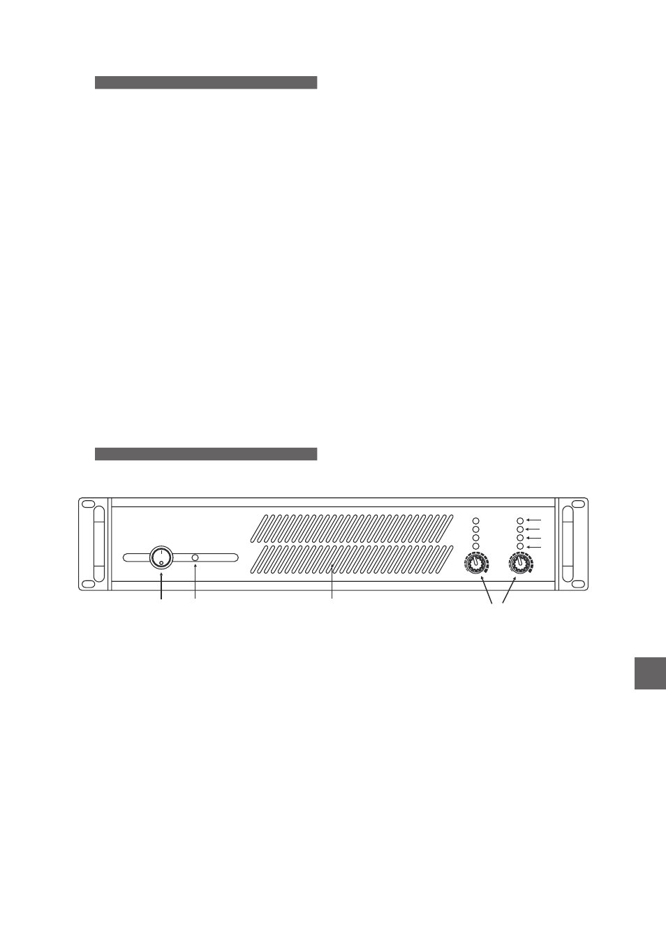
FRONT PANEL DESCRIPTION
A) Power switch
Turns the amplifier on (“|” position) and off (“0”
position). When the amplifier is turned on the
‘Power’
LED
and
the
protection
LEDs
will
illuminate.
When
all
voltages
are
properly
established the protection LEDs will turn off and
the ‘Power ON’ LEDs will remain illuminated. It is
of the monophasic type (which must be taken into
consideration if the device is to be permanently
connected to the mains power socket; see Safety
Warnings.
B) Power led
When lit, this red LED shows that the amplifier
is on.
C) Input level controls
Volume
levels
for
each
channel
can
be
adjusted by using the knobs found on the front
panel. Gain is maximum when the LEVEL rotary
potentiometer is rotated fully clockwise.
D) Clip led
In the event that the signal’s excursion exceeds
the maximum voltage from the power supply, the
unit will indicate saturation through the clip LED of
the channel involved.
E) Protection led
When a channel’s output is disconnected by
the amplifier’s protection, this yellow LED
illuminates.
A channel’s protection may be triggered by:
?
?
Overheating sensed at any part of a
channel. When the amplifier has cooled down,
the channel’s output will be connected and
operation will resume. The control circuit has
some degree of built-in hysterisis to avoid turn-
on and off oscillations.
Presence of DC at a channel’s output.
Since it may severely damage speakers, the
amplifier will deactivate the output in the event
DC levels are detected. Once DC is no longer
present, the PROTECTION LED will turn off
and output is reactivated.
?
?
Short-circuit (or too low impedance) at a
channel’s output. Although this protection is
provided, it is dangerous for the amplifier to
remain in this situation for a long time. In case
of a short-circuit, turn off the amplifier while
examining any equipment connected to the
amplifier’s
output,
together
with
the
connections and cabling. Once the short circuit
problem is corrected the amplifier needs to be
switched off and on to be reactivated. The
output will not reactivate automatically.
When the amplifier is switched on, the
output is also deactivated for a few seconds to
prevent dangerous transients from damaging
the speakers, and the PROTECTION LED is on
until the amplifier is ready for use.
Protection
Clip
Signal
Power On
Level A
Level B
POWER
A
B
B
F
E
D
C
G
EN
Manual del Usuario
/ CSA / User’s Manual