Crosman 1720T User Manual
Page 6
6
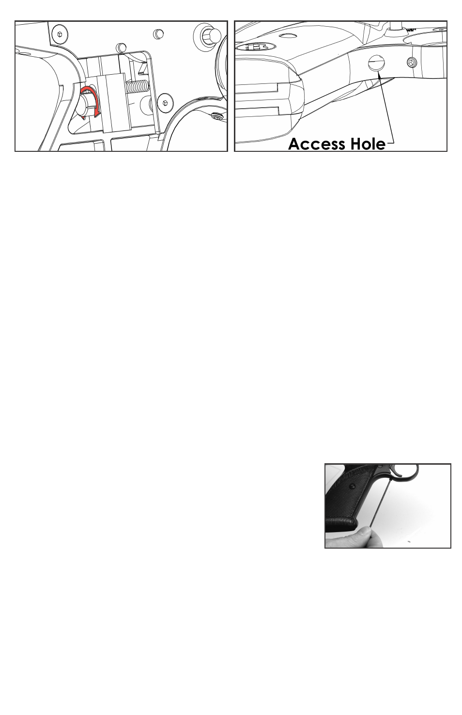
Fig 10A
Fig 10B
B. Two Stage Trigger Adjustment
•
Trigger Stage Adjuster Screws: Locate the stage adjustment screws access hole on the underside of
the Grip Frame (Fig. 9B). Using a .050” Allen wrench for adjustment of screws (A) and (B), changes can be
made to the position and length of first and second stages of the trigger motion. These adjustments could
affect sear engagement, and therefore could allow the gun to fire when dropped or jarred.
• Screw (A) changes the first stage. Turning screw (A) clockwise will increase the length of the first stage
and decrease the sear engagement. Turning counter clockwise will decrease the length of the first stage
and increase the sear engagement.
• Screw (B) changes the second stage. Turning screw (B) clockwise will cause the second stage to occur
sooner while turning counterclockwise will cause the second stage to occur later.
• Adjustment of screws (A) and (B) should be done in harmony with each other as they work together to create
the trigger’s profile. Start slowly to understand what each adjustment does and its relationship to the other.
• After adjusting your trigger, always check that the trigger and safety are functioning properly. If you are not
sure if the trigger or safety is operating properly, take your gun to an experienced gunsmith.
• Replace the Grip and Grip screw.
C. Single Stage Trigger Adjustment
•
Trigger Stage Adjuster Screws: Locate the stage adjustment screws access hole on the underside of
the Grip Frame (Figure 9B).
• For creating a single stage trigger, adjust screw (A) clockwise until the desired Sear engagement is
attained. Adjusting screw (A) in this manner will eliminate engagement of screw (B) and will yield the
lightest possible single stage trigger pull. Screw (B) can also be utilized to create single stage trigger by
turning in clockwise until the desired Sear engagement is attained. It is advised to also turn Screw (A) out
counter-clockwise a few turns to ensure it is no longer engaged at any point. Which screw is utilized to
create the single stage trigger depends on the preference of the individual.
• After adjusting your trigger, always check that the trigger and safety are functioning properly. If you are not
sure if the trigger or safety is operating properly, take your gun to an experienced gunsmith.
• Replace the Grip and Grip screw.
D. Maintaining the Marauder Pistol Trigger
• The Marauder pistol trigger is assembled with a moly graphite EP grease that should last for years. In the
event your trigger becomes contaminated with debris and is not functioning properly, contact a qualified
gunsmith to examine for repair or necessary maintenance.
E. Adjusting the Trigger Over-travel
• To ensure crisp, consistent action of the trigger, a set screw has been
incorporated into the trigger guard to allow each shooter to set the
trigger over-travel to their preference. Removing the screw will give the
most over travel, tightening the screw all the way in will stop the trigger.
Shooters will find their preference somewhere in between.
• Make sure the air pistol is unloaded (section 4B) and de-gassed (section 3D)
• Turn the set screw (H) as shown in Figure 8, all the way in with a hex wrench.
(not included)
• Cock the bolt by pushing the bolt handle up and pulling it all the way
back. Close the bolt and push the bolt handle down to lock.
• Point the air pistol in a SAFE DIRECTION, take “OFF SAFE” (section 2B) and pull the trigger. If the pistol
does not fire, turn the set screw counter clockwise in ½ turn increments until it fires.
IMPORTANT! Turn an additional ½ turn counter clockwise. This is important to ensure proper operation of
the trigger.
• Put the air pistol “ON SAFE”.
10. Adjusting for Various Fill Pressures and Velocities
• Proper adjustment of the 1720T requires use of a chronograph.
• The 1720T has been factory set for a fill pressure of
2900 psi and velocity up to 750 fps. These settings
will suit most target uses and will yield a long usable shot string. If you, as the owner, wish to alter the fac-
tory settings you should do so only after reading the following instructions carefully.
Fig 11