Rj45 null-modem cable, Rs-232 null-modem cable, Rs-422 null-modem cable – Comtrol Cable User Manual
Page 23: Rj45 straight- through cable, Rs-232 and rs-485 straight-through cable, Rs-232 null-modem cable rs-422 null-modem cable, Rj45 straight-through cable
Building Cables for DeviceMaster Products
[Documentation number: 2000430 Rev B] 23
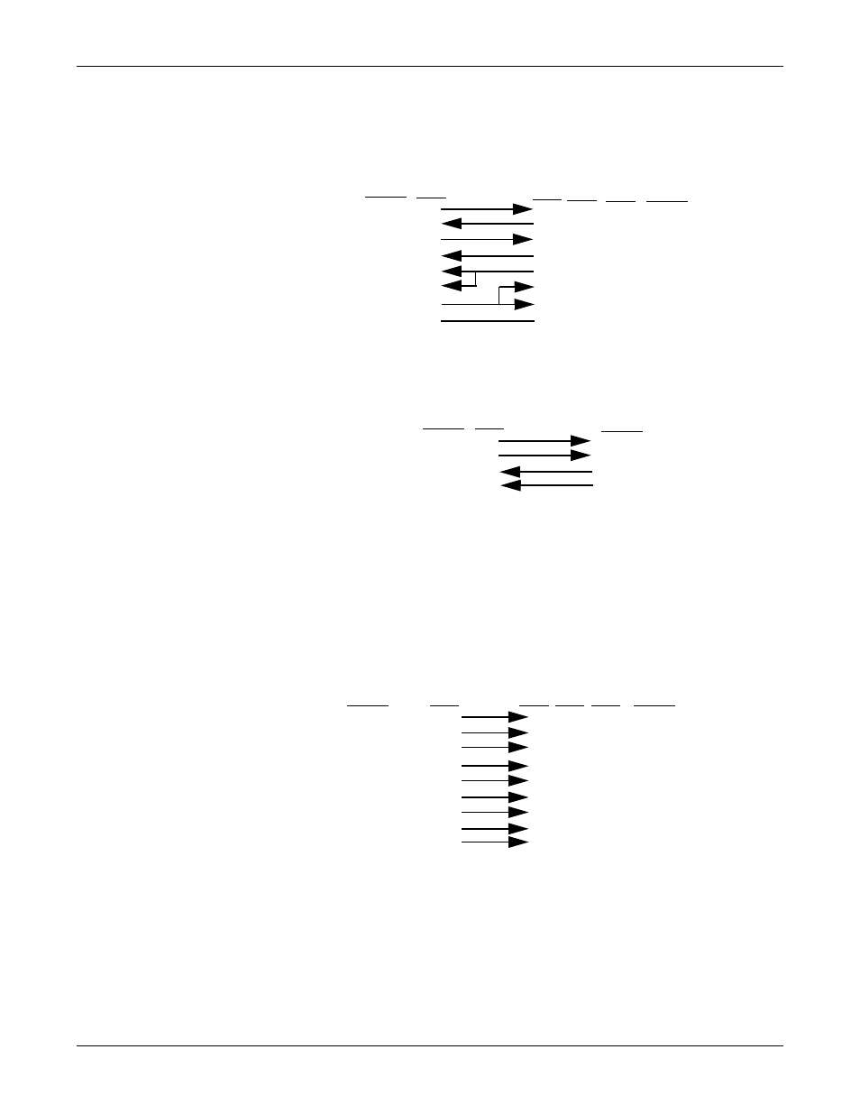
RJ45 Null-Modem Cable
RJ45 Null-Modem
Cable
You need a null-modem cable to connect to DTE devices. For example, you can
connect one end of a null-modem cable to COM2 on a computer and the other end
of the null-modem cable to COM2 on another computer.
RS-232 Null-Modem
Cable
The following image displays the pinouts for an RS-232 null-modem cable.
Note: You can also attach a null-modem adapter to one end of a straight-through
cable to create a null-modem cable.
RS-422 Null-Modem
Cable
The following image displays the pinouts for an RS-422 null-modem RJ45 cable.
Important:
RS-422 pinouts are not standardized. Each peripheral
manufacturer uses different pinouts. Please refer to the document
for the peripheral device to determine the pinouts for the signals
in the previous picture.
RJ45 Straight-
Through Cable
Straight-through cables connect modems to other DCE devices. For example, you
can connect one end of a straight-through cable to COM2 on one computer and the
other end of the straight-through cable to a modem.
RS-232 and RS-485
Straight-Through
Cable
The following image displays the pinouts for an RS-232 or RS-485 straight-
through cable.
Note: If your RJ45 wiring differs from the one shown above, adjust the RJ45
pinouts accordingly.
Dev
ice
M
a
s
te
r
TxD
RxD
RTS
CTS
DSR
GND
DCD
DTR
Signal
RxD
TxD
CTS
RTS
DTR
GND
DCD
DSR
Signal
DB9
2
3
8
7
4
5
1
6
Pins
DB25
3
2
4
7
8
6
Pins
RJ45
4
5
1
8
7
3
6
2
Pins
20
5
Fe
m
a
le
RJ45
5
4
1
3
6
7
Pins
2
8
De
vic
eMaster
TxD+
TxD-
RxD+
Signal
RJ45
1
4
8
Pins
Fe
m
a
le
RxD+
RxD-
Signal
RJ45
Pins
RxD- 5
TxD+
TxD-
De
vic
eMa
s
te
r
DB9
1
2
3
4
5
8
6
7
Pins
DCD
RxD
TxD or TRx-
DTR
GND
CTS
DSR
RTS or TRx+
Signal
DCD
RxD
TxD or TRx-
DTR
GND
CTS
DSR
RTS or TRx+
Signal
Fe
m
a
le
RI
9
RI
RJ45
6
5
4
2
3
8
7
1
Pins
N/A
RJ45
6
5
4
2
3
8
7
1
Pins
N/A
DB25
8
3
2
20
7
5
6
4
Pins
22