Modbus raw data addressing, Received message format, Modbus raw data addressing received message format – Comtrol Modbus TCP Quick Start User Manual
Page 25
DeviceMaster UP Modbus/TCP Quick Start: 2000477 Rev. G
Configuring Read-Only Raw/ASCII Devices - 25
Configuring Read-Only Raw/ASCII Devices
Modbus Raw Data Addressing
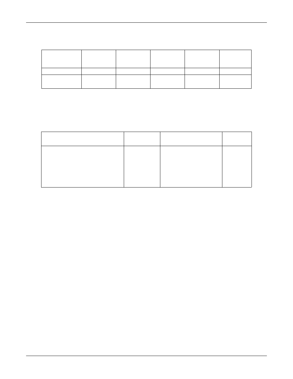
The serial port receive data addresses used for polling:
Received Message Format
If all is set up correctly, the data packets will be written into the PLC memory space starting at the specified
memory location. The first word received is the sequence number. This is incremented with each new data
packet. The next word is the length, which indicates the number of data bytes received. The rest is data.
The format of received serial data sent to or returned to the PLC:
General requirements:
•
The memory area must be defined in 16 bit words and large enough to handle the largest serial packet
plus two words for the produced sequence number and data length parameters.
•
The Maximum Rx Data Packet Size must be set large enough to accept the largest possible packet.
•
For large received data packets over 246 bytes (This may be less for your PLC):
The Rx (To PLC) Transfer Mode must be set to Master (Write to PLC).
-
The data will automatically be placed in continuous memory.
-
All data will have been transferred to the PLC when the sequence number is updated.
Serial Port
Raw/ASCII
Addressing
Serial Port 1 Serial Port 2 Serial Port 3 Serial Port 4 Access Rule
Unit ID
255 (FF Hex)
255 (FF Hex)
255 (FF Hex)
255 (FF Hex) N/A
Receive Data
Address
1000 (Base 0)
1001 (Base 1)
2000 (Base 0)
2001 (Base 1)
3000 (Base 0)
3001 (Base 1)
4000 (Base 0)
4001 (Base 1)
Read Only
Name
Data Type
Data Value(s)
Access
Rule
Receive (DeviceMaster UP to PLC)
message data.
Structure of:
Produced data sequence
Data length (in bytes)
Data array
WORD
WORD
Array of
WORD
0-65535 (
FFFF Hex
)
1-1024 (Master Rx Mode)
0-246 (Slave Rx Mode)
0-65535
Get