Acta-relief – Comfort Company Acta-Relief Quick Release User Manual
Page 2
ACTA-RELIEF
Parts Included:
1 - Complete Acta-Relief
®
Assembly with Quick Release Compass Hardware (2 Point)
1 - 5 mm Hex Key
1 - 2.5 mm Hex Key
Loosen the two clamp bolts (A) on both sides using the 5mm Hex Key. Tighten the clamps onto the left and right wheelchair canes.
The triangle brackets adjust in and out to accommodate varying sized wheelchairs. The Acta-Relief® can fit onto a wheelchair
1" narrower to 1" wider of the purchased size.
Tip: Make sure the clamps are the same height relative to one another on the canes.
Tip: Make sure the clamps sit square to the wheelchair.
Note: The quick release levers may be tight when first actuated, but will loosen after 1-3 times.
1
Slightly loosen bolts (B) above and below the triangle on both sides using the 5 mm Hex Key. Slide the triangle in or out until the
wheelchair canes are relaxed.
2
Gently loosen bolts (I) and (J) on both sides to allow for adjustment of all mounting brackets using 1/8 in. Hex Key.
1
Attach the cane mounts (G) facing forward as shown at the desired height, keeping each cane mount symmetrical. To attach the cane
mount, remove one side screw securing the metal strap, wrap the strap around the cane, tighten both side strap bolts, and tighten the
rear screw to secure.
2
Place the mounting pegs (H) into the grooves on the cane mounts (G) on both sides.
3
When hardware is properly placed, be sure to secure bolts (I) and (J) tightly on both sides.
4
Angle and Depth Adjustment: Loosen the two bolts (D) on both sides using the 5 mm Hex Key. The backrest can be slid forward/back-
wards, and can also be rotated angularly. Tighten all four bolts when the backrest depth and angle are adjusted.
5
Tighten set screw (E) on both sides using the supplied 2.5 mm Hex Key to lock angle rotation. These set screws intersect with the top
bolts and prevents angle rotation.
6
Tighten set screw (F) on both sides using the 2.5 mm Hex Key to prevent vertical movement and angular rotation of the clamps.
7
If the backrest was able to be removed and reinstalled smoothly, no additional height adjustments are needed. If further adjustments
are needed, repeat step 3. Fully tighten bolts (B) when adjustments are complete using 5 mm Hex Key.
4
Triangle Height Adjustment: Make sure the left and right triangles are at the same height relative to one another on the backrest shell.
When triangles appear to be in line, finger-tighten bolts (B) on both sides, open quick release levers (C), and remove/install the
backrest.
3
The installation of the backrest is complete. Adjustments for depth, angle, and height can now be made.
The user can be seated during this process.
IMPORTANT: When installation and adjustments are complete, all bolts should be tightened
to a minimum of 85 in-lbs.
*This does not include set screws.
Refer to 2 Point instructions # 1 - 7.
®
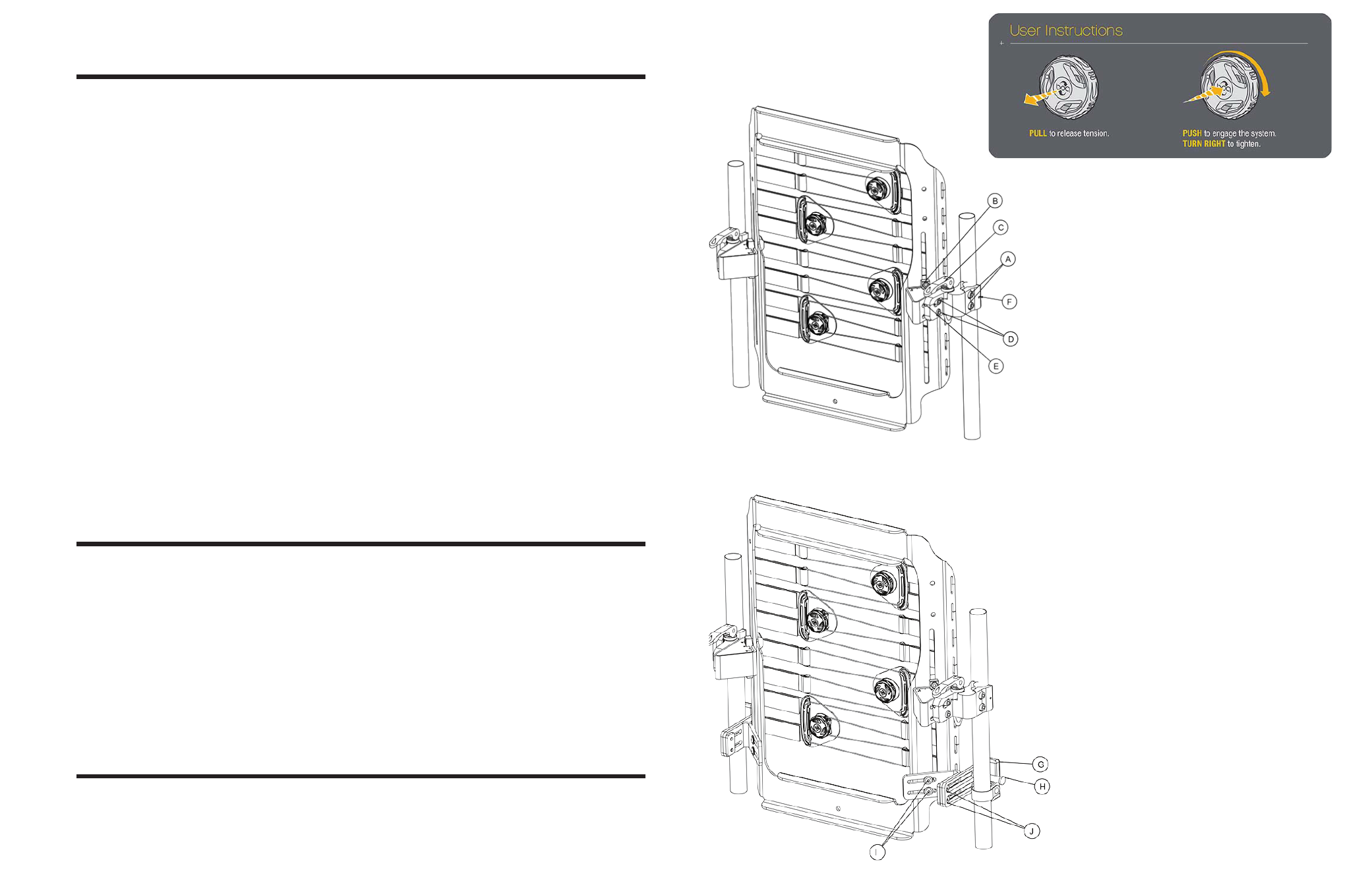
Attaching Quick Release Compass Hardware (2 Point)
Attaching Quick Release Compass Hardware (4 Point)
Attaching Quick Release Compass Hardware (2 Point)
Attaching Quick Release Compass Hardware (4 Point)
Parts Included:
1 - Complete Acta-Relief
®
Assembly with Quick Release Compass Hardware (4 Point)
1 - 1/8 in. Hex Key
1 - 5mm Hex Key
1 - 2.5mm Hex Key
The BOA
®
Advantage
MICRO-ADJUSTABLE:
Each click of the Boa
®
reel offers one millimeter of precision fit adjustment.
SECURE:
Once the Boa
®
reel is locked into place, it stays that way.
CUSTOMIZABLE FIT:
Boa
®
delivers smooth, even adjustment with no pressure points for maximum comfort.
CONVENIENT:
The Boa
®
closure system offers and adjustment solution free of messy straps, ratchets, and fasteners.