Comfort Company Comfort Foot Single User Manual
Comfort foot single 1 2 3 4, Bolt on, Clamp on
WARNING:
Make sure all screws are tightly clamped upon completion.
Toll Free 800.564.9248
www.comfortcompany.com
509 South 22nd Ave Bozeman, MT 59718
COMFORT FOOT SINGLE
1
2
3
4
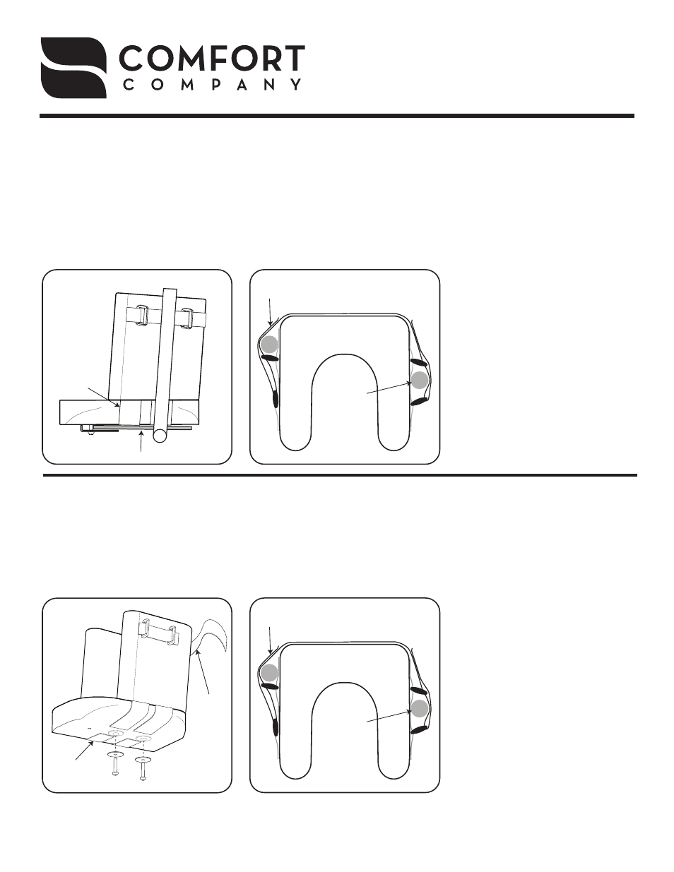
Clamp On
Parts Included:
1 - Clamp Assembly
Loosen (do not remove) footplate
clamp bolt using Phillips head
screw driver.
Slide clamp over wheelchair
footplate as seen in Diagram 1A.
Adjust Comfort Foot Single angle
to desired position using base
straps and tighten clamp bolt
securely.
Release side strap and secure
tightly around leg rest tubing (C).
Note: Depending on the wheel-
chair, strap will have to be tight-
ened in either configuration (A)
or (B) as seen in Diagram 2A.
Bolt On
Parts Included:
2 - ¼-20 x 1” or ¼-20 x 1 ¼ ” Screws (dimensions vary depending on style of part)
2 - ¼ ” x 1 ¼ " OD Fender Washer
1
2
3
4
5
Place the provided template on
the wheelchair footplate in the
desired position.
Drill two 5/16” diameter holes
through the footplate as marked
on the template.
Adjust Comfort Foot Single to
desired angle using base straps.
Screw two ¼-20 x 1” or ¼-20 x
1 ¼ ” bolts with the provided
washers from the bottom of the
footplate into the Comfort Foot
Single base. Note: Use 1“ bolts
for Comfort Foot Single with Gel.
Release side strap and secure
tightly around leg rest tubing (C).
Note: Depending on the wheel-
chair, strap will have to be tight-
ened in either configuration (A)
or (B) as seen in Diagram 2B.
IS-COMFORTFOOTSINGLE
REV0814
Diagram 1A (steps 1-3)
Diagram 2A (step 4)
Leg Rest Tube
Base Straps
Base Straps
Side
Strap
Side
Strap
Footplate
Clamp & Bolt
Wheelchair Footplate
A
B
Top View
C
C
Side
Strap
Top View
A
B
C
C
Diagram 2B
(step 5)
Diagram 1B
(steps 3-4)
Leg Rest
Tube
Leg Rest
Tube