3 4mi fcwrik, 4»4 c, I* pill assigiim#irts – Toshiba IK-CU43A User Manual
Page 7
Attention! The text in this document has been recognized automatically. To view the original document, you can use the "Original mode".
4.3
4MI fcwrik
]
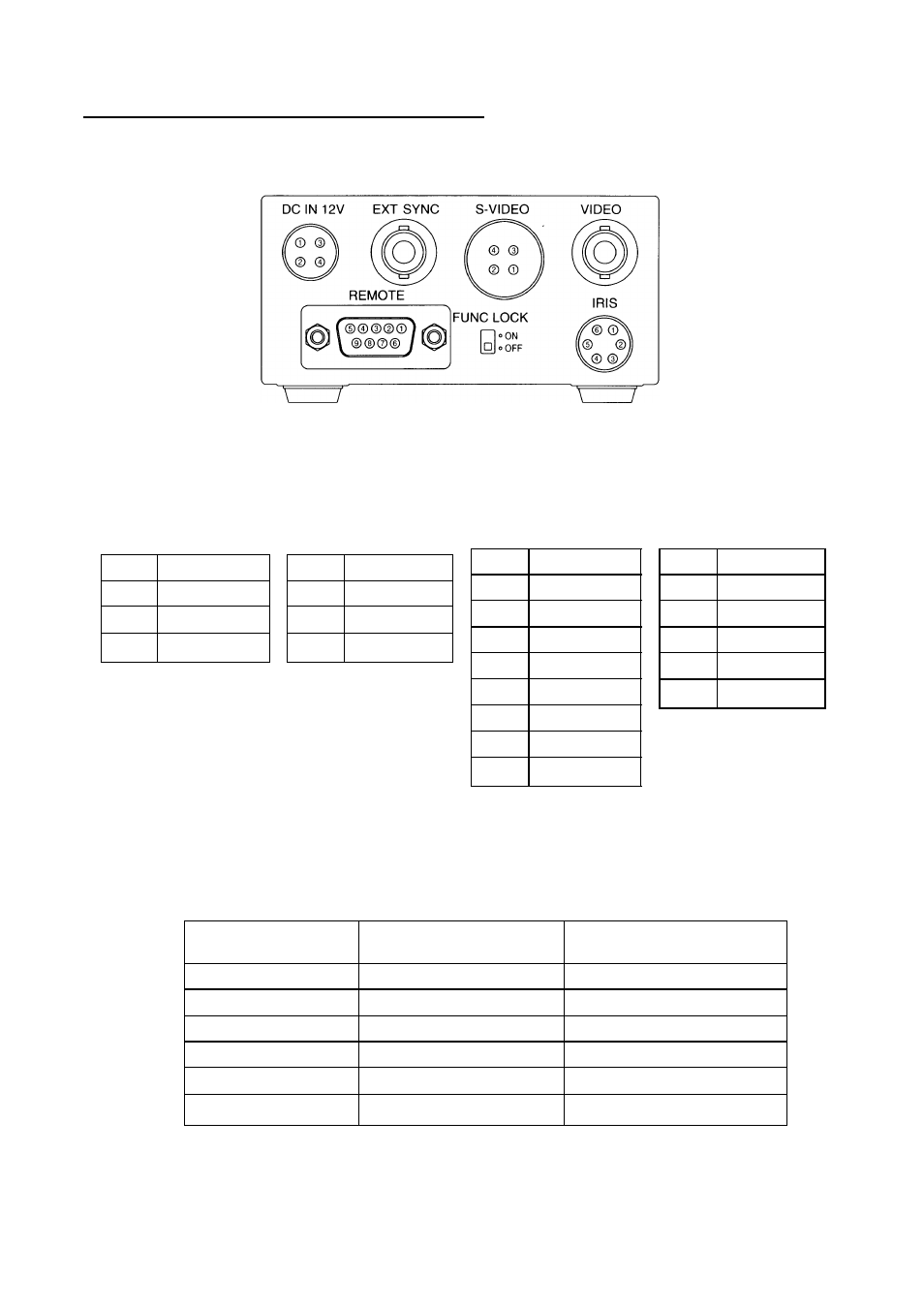
The figure below shows the back panel connection terminals of the camera control unit.
4»4 C
0
iiiieiHl
0
i* Pill AssigiiM#irts
DC IN 12V
S-VIDEO
1
+ 12V
2
+ 12V
3
GND
4
GND
REMOTE
1
GND
2
GND
3
Y
4
C
1
NC
2
TXD
3
RXD
4
DSR
5
GND
6
DTR
7
CTS
8
RTS
9
NC
IRIS
1
NC
2
VIDEO
3
GND
4
+ 12V
5
GND
6
NC
* When using the REMOTE terminal, please consult with your dealer.
Using the auto-iris lens
The following table shows the IRIS terminal when using the auto-iris (EE) lens.
Table 1
IRIS Connector
Terminal No.
Signal
Rated
1
—
2
Video signal
0.8± O.IVp-p
3
GND
4
Power (DC)
+ 12V (less than 50mA)
5
(GND)
6
—
The IRIS connector used for the IRIS terminal: HR10A-7P-6P of HIROSE ELECTRIC
CO., LTD.