Rear panel, Rear panel é – Toshiba KV-6200A User Manual
Page 6
Attention! The text in this document has been recognized automatically. To view the original document, you can use the "Original mode".
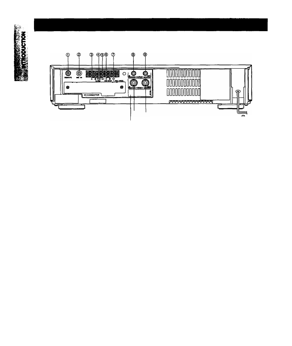
Rear Panel
é
®
BATTERY cover
® REMOTE jack
Accepts the plug from the remote control.
®
MIC IN jack
Accepts audio signals from a microphone, in this case the
RCA jack input will be switched off.
®
ALARM IN terminal
Signal input terminal to start alarm recording.
The VCR goes to alarm recording mode when the terminal
is connected to the ground terminal during recording.
® ALARM RESET terminal
Signal input terminal to release alarm recording.
Alarm recording is released when the terminal is con
nected to the ground terminal during alarm recording.
(D ALARM OUT terminal
Output terminal to transmit the alarm signal to an external
equipment.
A voltage of DC +5V is output during alarm recording.
® ONE SHOT IN terminal
■' Used for One-shot recording.
® REC TRIGGER OUT terminal
Signal output terminal to control the switching timing of tiie
camera when connected writh the sequential switcher.
® AUDIO IN jack (RCA type)
Used to record external audio signals by connecting to the
audio output jack of an external audio source.
. ® AUDIO OUT jack (RCA t^)
Used to connect to the audio input jack of external audio
equipment.
® VIDEO IN connector (BNC)
Used to record external video signals by connecting to the
video output jack of an external video source such as a
camera, etc.
® VIDEO OUT connector (BNC)
Used to connect to a monitor TV.
® POWER CORD
Insert to an 120V AC outlet.
Note:------------------------------------------------------------
This VCR allows recording of characters and numerical
information sent from the ATM (Automatic Tetter Machine),
Cash Register and superimposed on the screen by cwinect-
ing the specified l/P (Interface Board) to tire I/O connector on
rear of the unit.
When you wish to obtain the t/F Board, please consult
TOSHIBA AMERICA C.P. INC. (See MANUAL Back cover)
The mounting of the 1/F Board is allowed only by a qualified
service man.
For details on the mounting, refer to the Instruction Manual
supplied with the 1/F Board.