Important notes, Maintenance, 2^-6-h – Graco 226-167 SERIES"A" User Manual
Page 7: Service diagnosis, Preventive maintenance
Attention! The text in this document has been recognized automatically. To view the original document, you can use the "Original mode".
PREVENTIVE MAINTENANCE
At least twice daily and during any lengthy
interruption
of
spraying,
with
material
pressure
relievedi remove and clean gun spray tip and tip
filter in clean solvent of a type recommended by
manufacturer
of
the
material
being
sprayed.
Blow-
parts
dry
with
air
pressure.
Also
inmerse
gun
nozale in clean solvent during shut down periods.
SHUTDOWN PROCEDURE
To maintain efficient operation of unit,
this shutdown procedTu:e at the completion of
each day’s spraying must be diligently followed:
1.
Shut off air to pump by closing p-ump
ON-OFF air control petcock 202-338« See Fig. 1.
Handle is at right angle to petcock body vdien
closed.
2.
Relieve material pressure in p\unp, hose
and spray gun by opening drump valve of manifold.
This will allow the material trapped in the system
to drain back into material container. After ma
terial has stopped draining, remove and clean
filter cartridge or screen. If used. Close drain
valve.
3.
Remove spray tip and filter, if used,
from spray gun. Immerse in clean recommended
type solvent and wash thoroughly with a fine
bristled brush. Using the air blower valve
205
-
5
W- attached to air manifold 162-376, blow
air through tip from front to back and through
open end of filter. Refer to Fig. 1. Keep
spray gun forward end submerged in clean re
commended type solvent until ready to start
spraying again. NOTE:
Do not remove the spray
gim from dispensing hose unless the unit is to be
completely flushed. Keeping unit fully charged
with material will minimize the necessity for
flushing unit.
CAUTION! Water based paints will recpiire a
final flushing with solvent DAILY and also oiling
of all external moving pump parts to prevent the
rusting of the wetted parts. To completely flush
unit follow the procedure outlined in subsequent
paragraph entitled FLUSHING UNIT.
'SERVICE DIAGNOSIS'
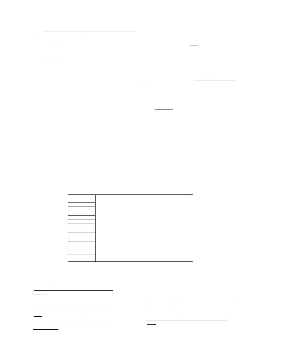
TROUBLESOME SYMPTOMS
Pump fails to operate, no material discharge.....................................
Pump operates, but insufficient material discharge.
Excessive surge at spray gun..............................................................
Insufficient material breakup.............................................................
Tails In spray pattern..........................................................................
Spray gun spitting..............................................................................
Too heavy a coating thickness...........................................................
CHECK POINT NOS.
1- 3-A-6-8-9
2- 4-7-U
1-2-9-10-12
1-2-3-4-6-9-11
1-2^-6-H
13
5
-
10-11
CHECK POINT N0.
POSSIBLE CAUSES
1................ Restricted air supply line.
2................ Insufficient air capacity.
3................ Air valve closed or clogged.
4................ Air regulator inoperative or set too low.
5................ Air regulator set too high.
6................ Material too viscous
7................ Insvifficlent material in container.
8................ Clogged material intake strainer.
9................ Clogged material filter, tip or tip filter.
10................ High flow rate—tip orifice too large.
11................ Improper or worn spray gun tip.
12................ Surge chamber inactive, if used.
13................ Worn, damaged or obstructed gun parts.
14................ Worn or obstructed pump valves or packings.
MAINTENANCE
IMPORTANT NOTES
1.
Keep unit, mixing container, thinner.
solvent, and material CLEAN and free of foreign
particles i-ihich could clog strainer screens and/
or plug the small orifice in spray tip.
2.
Keep lower pump Assembly filled with
and spray gun head immersed in recommended type
clean solvent after flushing unit and until
ready to start spraying again.
3.
To relieve unit of unnecessarT pressure
vdien not in use, shut off air pressure to pump
and
relieve
material
pressure
in
system
by
opening
dxunp valve of manifold or filter.
4.
Daily or more often if experience in
dicates necessary, drain filter or surge tank, re
move filter cartridge or screen, if used, and
clean. Before draining tank and removing filter
cartridge or screen, shut off air pressure to pump
and relieve matf>r-i.al pressure bv opening dump
valve. Replace cartridge or screen after cleaning
and close d-ump valve.