Air requirements, Preparation for operation – Graco 226-167 SERIES"A" User Manual
Page 4
Attention! The text in this document has been recognized automatically. To view the original document, you can use the "Original mode".
This equipment has been carefully manufac
tured to exacting CHACO standards. It is war
ranted against defective materials and/or work
manship as set forth in the GRACO WARRANTT.
Excessive wear due to passage of abrasive or
corrosive materials through this equipment shall
not be construed as indication of defective parts
within the limitations of this warranty.
IMPORTANT NOTES
•*PTFE * material hose is expensive. HAHPLE
WITH C
akjs
. GRACO WARRANTY does not cover abuse
such as sharp kinking, crimping or crushing.
Air supply hose 205-216 includes a static
wire to effectively ground the unit. If addi
tional air supply hose is required, it should
be of the same type.
AIR REQUIREMENTS
Air pressures required to operate pump range
from 20 to 100 p.s.i. CAUTION; Do not use more
than 100 lb. of air pressure to operate pump.
During continuous operation, at norTnal work
ing pressures and operating speeds, this unit will
reqviire actual air delivery of approximatelY ^
c.f.m. per gun plus 3 c.f.m. for continuous use of
agitator.
To provide reserve capacity for peak load
conditions compressor shovdd delivery
2 5 %
more air
than required for normal operation of all equip
ment vdiich It is to serve.
NOTE; Consumption of compressed air Is low.
since in this Hydra-Spray process air is not need
ed to atomise the paint.
PREPARATION FOR OPERATION
1, Remove contents from carton and connect
the wire-braided Dupont ’’
PTFE
*’ lined material
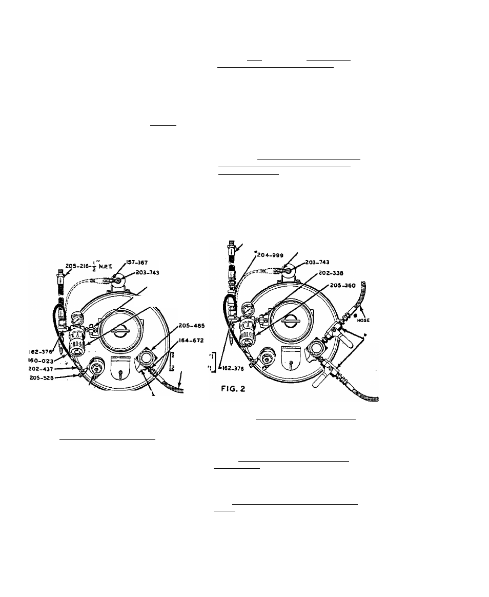
hose 205-3A9 (15') or 20A-yja ^25’) to nipple
161-672 protnidtng from material outlet manifold
205-485. Connect the end, without swivel 204-940
attached, to nipple 164-672. See Fig. 1. DO NOT
connect swivel 204-940, attached to other end of
this hose, to spray gun at this time. DO NOT USE
THREAD SEALER AT ANY SWIVEL CONNECTION.
202-338
'^^^^205-360
before reaching unit. NOTE; A Graco air line
strainer 204-999 (accessory) may be purchased
separately for removing foreign matter from air
entering the unit. Attaches to air manifold
162-376
as shown in Fig. 2.
,205-216--^V
p
T
THESE ARE
accessories
157-367
104-038 125
OR
05-349115
FIG. I 305-307
HORIZONTAL (CLOSED».
NOTE: Check dump valve of manifold 205-485
...it should be closed. When closed, its knob
is in a horizontal position. Refer to Fig. 1.
2.
For operation of a second spray gun
purchase these accessories separately...two (2)
high pressure material shutoff valves 205-583,
a second hose 205-349 (15')
204-938 (
25
*), a
second swivel 204-940, a second spray gun 205-162
and a second spray tip of customers choice. Re
move nipple 164-672 and plug from manifold
205-485, and qormect valves and hoses as shown
in Fig. 2.
' '
3
.
Attach one end of 15 foot air supply hose
205-216 to soiH-ce of air supply and screw other
end of hose into air manifold swivel adapter
162
-
376
.'' Refer to Fig. 1. Male hose studs are
threaded
^
NPT. Install a master air valve
(drain or bleed type)in the air supply line in
such location that air can be turned on and off
205-583
NOTE: Models 226-163. 226-165 & 226-167 are
equipped with a brake—to set brakes push down
with foot on rod protruding from bracket attached
to back of truck base and guide rod into notch at
bottom of bracket.
4. If Model
226-161
or 226-163 with hand
operated elevator, lift up on elevator hanger and
hook over handle. NOTE:
If elevator is difficult
to raise, apply a little grease to exterior svir-
faces of handle ends.
If Model
226-165
or
226
-I
67
with air-operated
elevator. disconnect air line coupler 202-437,
attached to end of air hose 160-023, from air line
fitting in agitator 205-307 and connect to air
line fitting
157-367
atop elevator as shown in Fig.
1, With air admitted to unit, elevator will raise
unit and hold it there until air hose 160-023 Ls
disconnected. '