Cabletron Systems 9H423-28 User Manual
Page 36
LANVIEW LEDs
4-2
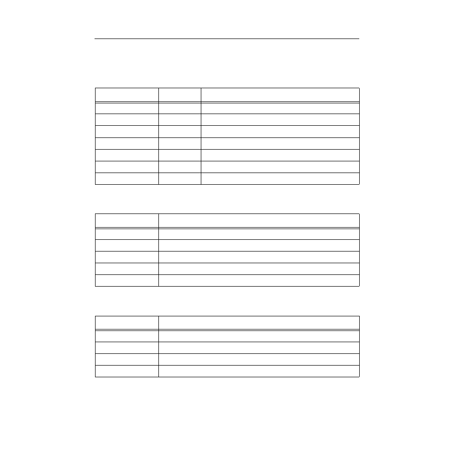
The function of the two System Status LEDs, System Management Bus (SMB) and
CPU (Central Processing Unit), are listed in Table 4-1.
The function of the INB Receive LEDs is listed in Table 4-2.
The function of the INB Transmit LEDs is listed in Table 4-3.
Table 4-1. System Status (SMB and CPU) LEDs
LED Color
State
Description
Green Functional
Fully
operational
Yellow
Testing
Power up testing
Yellow (Blinking)
Crippled
Not fully operational (i.e. one port may be bad)
Yellow/Green
Booting
Module is performing its boot process
Red
Reset
Module is resetting
Red (Blinking)
Failed
Fatal error
Off
Power off
Module powered off
Table 4-2. INB Receive LEDs
LED Color
State
Green
Link, no activity, port enabled
Green (Blinking)
Link, port disabled
Yellow (Flashing)
Link, activity, port enabled (Flashing to steady on indicates rate.)
Red
INB fault, (not synchronized with the Monarch)
Off
No link, no activity (port enabled)
Table 4-3. INB Transmit LEDs
LED Color
State
Green (Flashing)
Activity, port enabled (Flashing to steady on indicates rate.)
Yellow (Blinking)
Port in standby state
Red
INB fault
Off
Link (port disabled)