For ct1501 heating/cooling – Honeywell CT1503 User Manual
Page 9
Attention! The text in this document has been recognized automatically. To view the original document, you can use the "Original mode".
For CT1501 heating/cooling
□
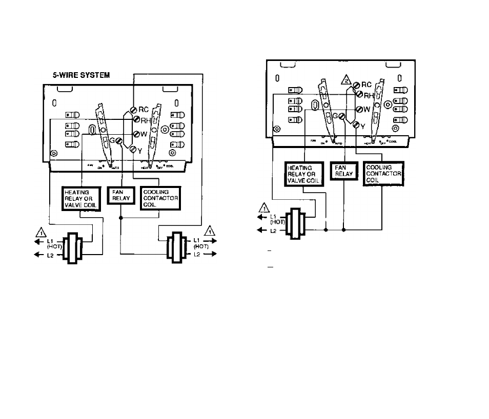
Connect the wires to matching terminals on
the subbase.
A
POWER SOPPLV, PROVIDE DISCONNECT MEANS AND
■ OVERLOAD PROTECTION AS REQUinED.
NOTE: If there are four wires, connect wire
marked R to terminal RH arid add a jumper
wire to connect to RC. If RC is left uncon
nected, the air conditioner will not turn on. The
4-wire drawing on this page shows how to jumper
RC to RH Strip the insulation off the wire
where it connects to the terminals. Firmly tighten
screws.
4-WIRE SYSTEM
A POWER SUPPLY. PROVIDE DISCONNECT MEANS AND
OVERLOAD PROTECTION AS REQUIRED.
A\
INSTALL JUMPER BETWEEN RC AND RH.
If the labels do not agree with the terminal
designations on your new subbase:
• Refer to Table 2 on page 8,
• Determine correct hookup from the listed
control function and the equipment control
circuit.
69-0273—9