Carl Goldberg GBGA1089 User Manual
Page 8
8
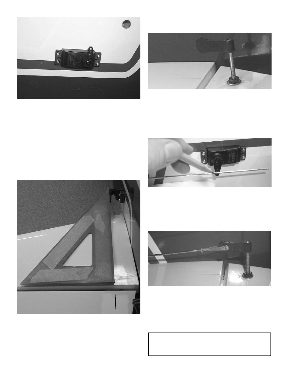
5.
With the servo in place, remount both stabiliz-
ers and make a mark at a 90º degree angle to
the elevator hinge line, and in line with the
servo arm.
Position the control horn bolt so that it is 3/4”
back from hinge line on the mark that you just
made.
6.
Using a 9/64" drill bit, make a hole in the ele-
vator through to the top side.
3.
At the rear of the fuselage just below the front
of the stabilizer you will find the servo cut outs
on both sides of the fuselage. The top cut out
is for the elevator servos.
Remove the covering over top of the elevator
servo hole
Mount your elevator servo with a 24” servo
extension taped to it.
4.
Pull the servo extensions towards the front of
the plane.
Repeat these steps for the second elevator
servo.
5.
Insert the 6-32 x 2” screw from the top through
the elevator.
Place the #6 washer and the 6-32 hex nut on
the bolt and tighten. Make sure that you use
thread lock on the bolt and nut.
Screw the black adjustable horn bracket on
the bolt.
6.
Thread the 2-56 hex nut and metal clevis onto
the end of the 2-56 x 7-7/8 pushrod.
Mount the pushrod onto the elevator control
horn.
7.
Keeping the elevator level, make a mark
where the pushrod touches the servo arm.
8.
Make a 90 degree bend at the mark you just
made.
Put the pushrod through the servo arm hole
and attach the swivel keeper.
Place a clives clip on each clevis.
Repeat for the other elevator.
Caution:
Make sure each snap link is fully closed with a
clevis clip before and after each flight.