Tail construction – Carl Goldberg GBGA1089 User Manual
Page 7
7
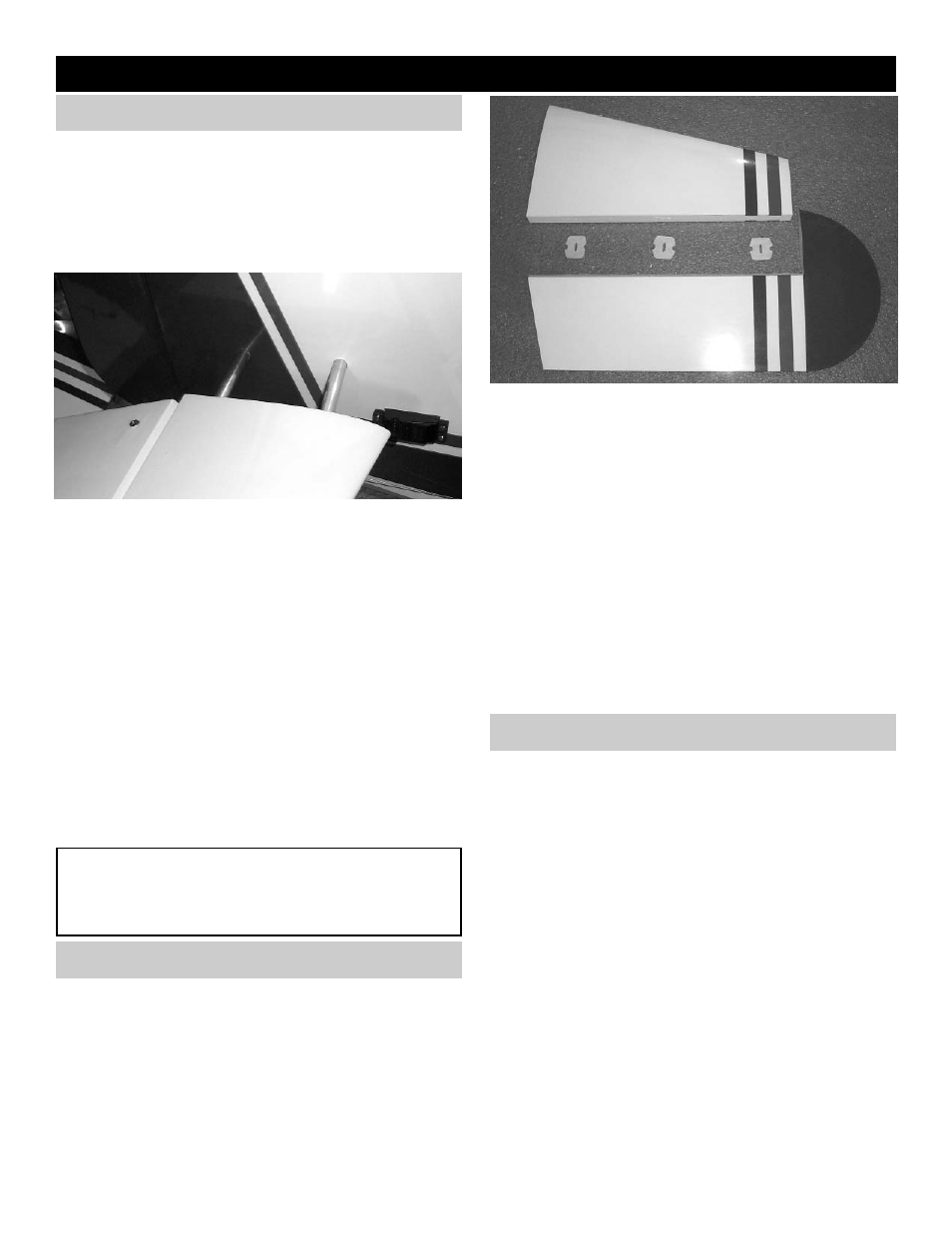
TAIL CONSTRUCTION
* Collect the following items
(2) Right & left Stab
(1) 10mm x 182mm front stabilizer tube
(1) 10mm x 312mm Rear Stabilizer tube
(2) 4-40 x 3/8 Socket head screw
1.
Slide the short stabilizer tube into the front
hole and long stabilizer tube in the rear hole of
one side of the stab. Then slide the assembly
into the holes in the fuselage till the stab is
flush against the fuse. (The side of the stab
with the hole is the top of the stabilizer). Slide
the second stab onto the tubes sticking out
the other side of the fuselage. Squeeze both
stab pieces together firmly on to the fuselage.
Check that the stabilizer is level with the wing.
Shim the tube in the fuselage up or down if
necessary. Do not go any farther till the stab is
level to the wing.
2.
Using 4-40 x 3/8” bolt, drill and tap the stabi-
lizer tube at both hole locations. This method
will allow you to remove the stab as needed.
Remember to keep the stabilizers tight
against the fuselage.
STAB INSTALLATION
CAUTION:
You must watch the bolt holes for fatigue and drill
another hole by rotating the tube when this hap-
pens.
HINGING THE ELEVATORS
Collect the following items:
(2) Elevators
(6) Hinges
1.
Take three hinges and, as with the aileron
hinge installation, insert the hinge into the ele-
vator, using straight pins to ensure the hinge
stays centered between the stabilizer and the
elevator.
Slide the exposed side of the hinge into the
slots in the stab until the pins touch both the
stab and the elevator.
2.
Remove the pins in each hinge and, keeping
the elevator/stab assembly in position, apply 3
or 4 drops of thin CA to each hinge, on both
the top and bottom sides of the stab.
Allow ten minutes for the CA to cure before
flexing the elevator. Then install the second
elevator.
INSTALLING THE ELEVATOR SERVOS
1. * C
OLLECT THE FOLLOWING ITEMS
:
(2) S
ERVOS AND MOUNTING HARDWARE
(6) 24” S
ERVO EXTENSIONS
(2) 2-56
X
7-7/8” T
HREADED
R
OD
(2) -2-56 M
ETAL
C
LEVIS
(2) N
YLON
S
WING
K
EEPER
(2) 6-32
X
2” F
LAT
H
EAD
S
CREWS
(2) 6-32 H
EX
N
UT
(2) #6 F
LAT
W
ASHER
(2) B
LACK
A
DJUSTABLE
H
ORN
B
RACKET
(2) 2-56 H
EX
N
UT
2.
Remove the stabilizer from the fuselage.