Elevator & pushrod – Carl Goldberg GBGA1082 User Manual
Page 7
7
3.
Spread epoxy on both the inside “V” of the
stab and the stab platform of the fuse.
Replace the stab on the “V” platform and,
check that the stab is resting completely flat.
Allow to dry.
Elevator & Pushrod
1.
Collect the following parts:
(1) Pushrod Assembly
(2) elevators
(2) Wooden control Horns
(2) Nylon Clevises
(6) CA Hinges
2.
Locate the pre-cut control horn slots in both
elevators.
Using a hobby knife (#11 blade), slide the
blade into each slot to make sure the covering
is cleanly cut. The slot is 3/8” from the end of
the elevators.
Making sure that the elevator is upright, insert
the wood control horn in the slot.
3.
Keep the control horn perpendicular to you
table top and the end flush with the top of the
elevator.
Slide the elevator into the “V” tail using the
hinges
4.
Repeat this process with the other elevator.
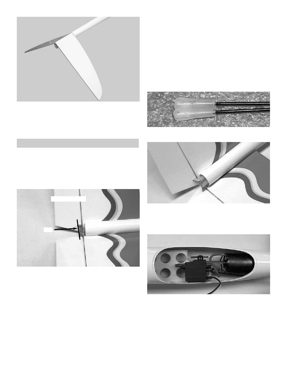
Align the two control horns so they are even
with each other. (See Photo)
Carefully pull the elevators back out of the “V”
tail and glue the control horns in place.
5.
Re-insert the hinges into the elevators and
placet them back onto the “V” tail.
Make sure the tip of the elevator is even with
the tip of the “V” tail.
Using thin CA, glue the elevators in place.
Align the control horns
Even
6.
thread the nylon clevises onto the end of the
elevator pushrod.
7.
Insert the pushrod into the rear of the fuse-
lage.
Make sure the front of the pushrod rest under
where the servo arm will be.
7.
Insert the elevator servo into the fuselage. (
We used a Futaba 3101 servo).
Making sure that the servo arm is straight to
the servo, mark the pushrod were the servo
arm hole meet.
Remove the pushrod from the fuselage.