Hardware hookup, Configuring the display, Crestron isys™ tps-tpi touchpanel interface – Crestron electronic TPS-TPI User Manual
Page 11
Crestron Isys™ TPS-TPI
Touchpanel
Interface
Hardware Hookup
NOTE: Review the Network Interconnection Diagram (latest revision of Doc.
5411) when making the network connection.
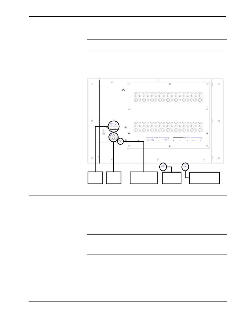
The TPS-TPI touchpanel can be placed on a flat surface or mounted with screws (not
supplied). Refer to the hookup diagram after this paragraph. Other than making the
power connection last, complete the connections in any order.
TPS-TPI Hookup Diagram
TO EXTERNAL
AUDIO
SYSTEM
FROM
AUDIO
SOURCE
TO
CONTROL
SYSTEM
TO EXTERNAL
TOUCH SCREEN
OR SERIAL MOUSE
CRESTRON ELECTRONICS INC.
ROCKLEIGH, NJ 07647 USA
TO LCD DISPLAY,
VIDEO PROJECTOR,
OR PLASMA MONITOR
Configuring the Display
To configure the unit, it may be necessary to access a series of setup screens prior to
viewing run-time screens that can be shown on virtually any display. The Main
Menu for configuring the display appears when a finger is held to the touchscreen as
power is applied. Remove your finger when the message "SETUP MODE" appears
on the touchscreen.
NOTE: If a touch-sensitive screen overlay is not being used, the "SETUP MODE"
can be achieved with a reserved join number (17242). Refer to "Reserved Join
Numbers" on page 21 for listing of other display settings and the respective join
numbers.
Upon entering SETUP MODE, the Main Menu, shown after this paragraph, displays
four buttons: Touch Screen Calibration, Exit and Run Program, Setup, and
Diagnostics.
Operations Guide - DOC. 5855
Touchpanel Interface: Crestron Isys™ TPS-TPI
• 7