Fig. 23 — flow switch, Bad good good fig. 24 — tank baffling – Carrier AQUAFORCE 30XA080-500 User Manual
Page 50
50
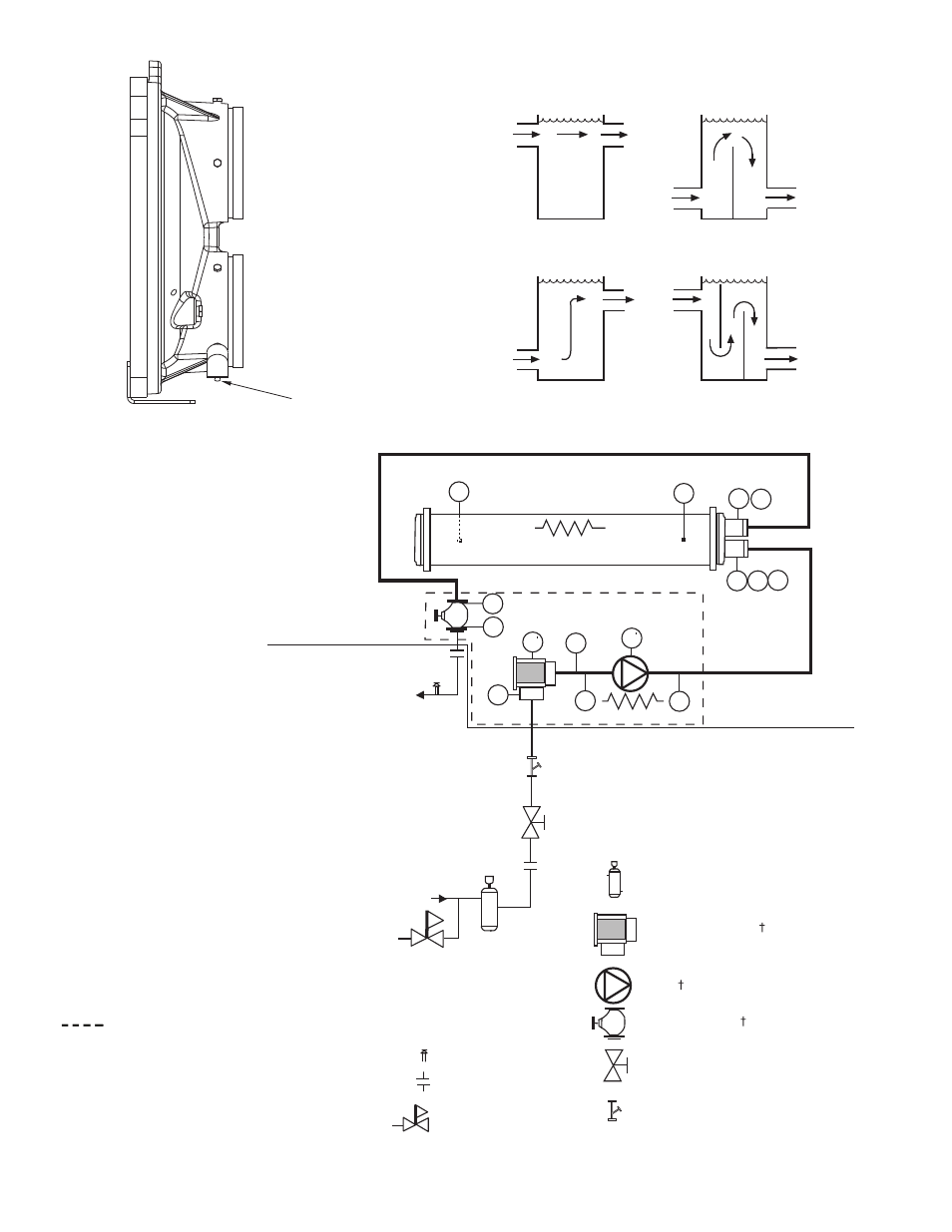
FLOW SWITCH
Fig. 23 — Flow Switch
a30-4138
BAD
BAD
GOOD
GOOD
Fig. 24 — Tank Baffling
a30-3185
PT
PT
T1
T2
FS
PP
PP
D
D
V
D
PT
PT
Chilled
Water In
Chilled
Water Out
Heater
Heater
E
PT
Air Separator with Vent*
Strainer/Suction Guide
Pump
Combination Valve
Isolation Valve*
Pressure Reducing
Fill Valve*
Flexible Connections*
Pressure Relief*
HYDRONIC PUMP PACKAGE
INSIDE
UNIT
OUTSIDE
UNIT
20 Mesh Stainer**
LEGEND
*Field-supplied and installed.
†Factory-installed option.
**Required for open loop systems.
D
— Drain,
3
/
4
-in. NPT
D
— Drain,
1
/
4
-in. NPT
E
— Expansion Tank Connection,
3
/
4
-in. NPT
FS
— Flow Switch
PP — Pipe Plug,
1
/
4
-in. NPT
PT
— Pressure/Temperature Tap
T1
— Leaving Water Thermistor
T2
— Entering Water Thermistor
V
— Vent,
1
/
4
-in. NPT
Indicates items provided with the
optional hydronic pump package.
Fig. 25 — Typical Piping Diagram on 30XA Units with Hydronic Package — Single Pump
a30-4414