Sk-acp installation & operating manual, Wiegand in – American Access Systems ProAccess 200sa User Manual
Page 9
SK-ACP
Installation & Operating Manual
WIRING
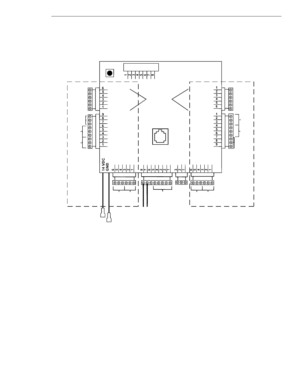
The SK-ACP unit is organized so that the wiring for door #1 is on the right side of the panel and the wiring for door
#2 is on the left side of the panel (see figure 3).
For ease of installation and servicing, plug-in terminal blocks are provided.
FIGURE 3
5
16.5-24 VAC
16-30 VDC
AUX
RELAY
1-B
AUX
RELAY
2-A
AUX
RELAY
2-B
AUX
RELAY
1-A
RS485
BUS
WIEGAND
IN
IN 2
COM
IN 1
NO
COM
NC
NO
COM
NC
NO
COM
NC
NO
COM
NC
AC
-
AC
+
I/O
TXD
RT
S
CTS
RXD
GND
GND
A
B
NO
COM
NC
NO
COM
NC
RS 232 PORT
RJ11 JACK
RED LED
GREEN LED
14 VDC
SIG GND
DATA 1
DATA 0
DATA 0
DATA 1
SIG GND
14 VDC
GREEN LED
RED LED
GREEN
WHITE
BLACK
RED
ORANGE
BROWN
BROWN
ORANGE
RED
BLACK
WHITE
GREEN
INPUT 2-2
INPUT 2-1
LATCH
RELAY
2 - A
LATCH
RELAY
2 - B
INPUT 1-1
INPUT 1-2
LATCH
RELAY
1 - A
LATCH
RELAY
1 - B
NC
COM
NO
NC
COM
NO
IN 1
COM
IN 2
J1
J4
J2
J6
J9
J7
J8
J3
J5
RESET
BUTTON
RS232
PORT
EXPANSION
DOOR 2
DOOR 1
EXP
. BRD
BLA
CK
BR
O
WN
RED
TO BATTERY
BACK-UP OR
12 VDC SUPPLY