1b+ ii water wizard water heaters he-110 – AERCO Packaged WaterWizard Steam-to-Water Heater User Manual
Page 13
1B+ II Water Wizard Water Heaters
HE-110
Installation, Operation & Maintenance Manual
OMM-0063_0C
MC2: 07/26/13 Page 13 of 50
AERCO International, Inc. • 100 Oritani Dr. • Blauvelt, New York 10913 • Phone: 800-526-0288
Installing the Water Wizard Heater Instructions (Cont.)
f) All drain discharges – relief valve(s) in the Top Head of the Heater, outlet of the
Water Solenoid Valve in the top head of the Heater, and Drain Valve in the Bottom
Head of the Heater – should be piped directly to a convenient floor drain.
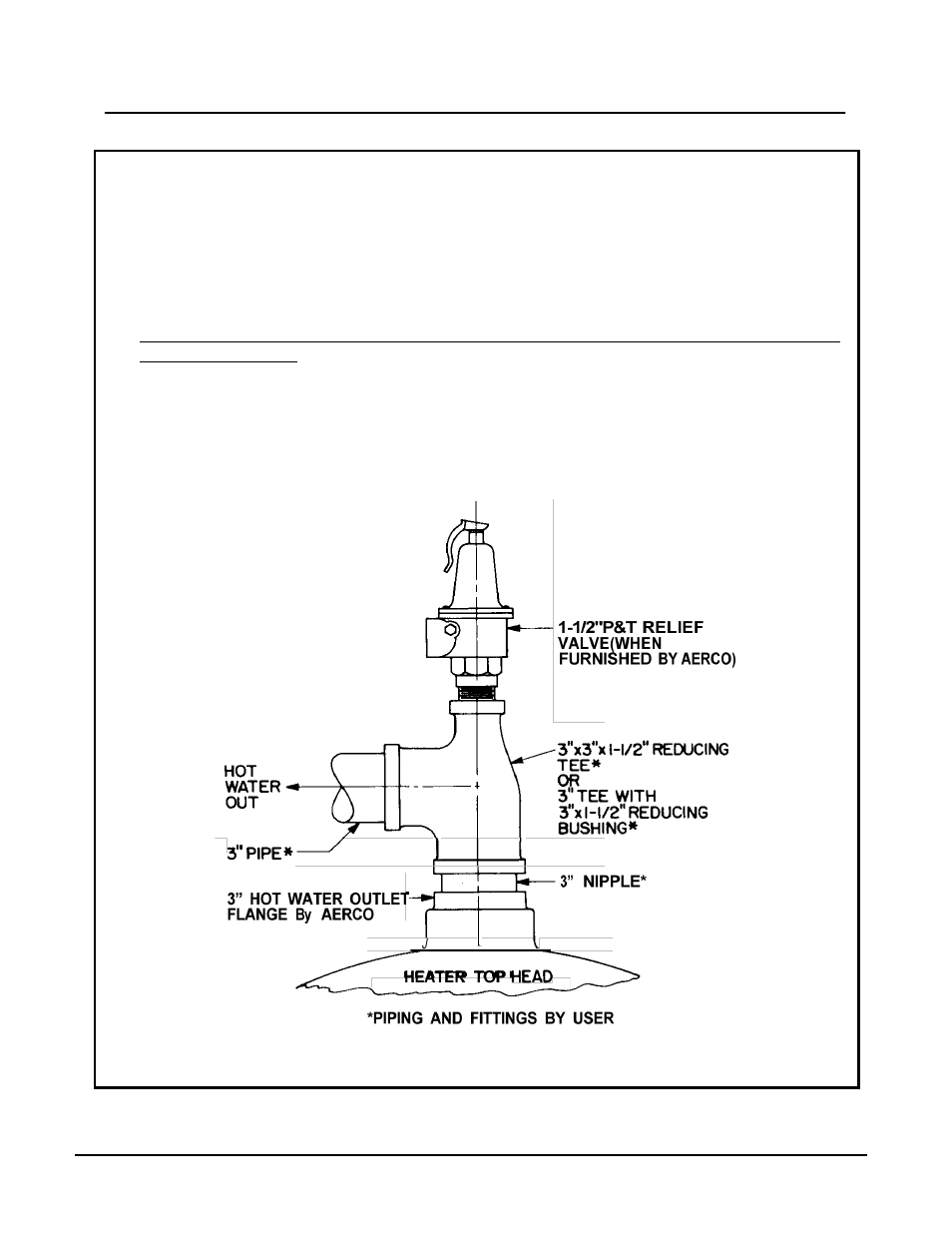
7) When a third P&T Relief Valve is furnished with the Heater (the first two furnished have
been assembled in the top head of the Heater by AERCO), the third Valve is to be installed
in the Heater hot water outlet piping, by the user, as illustrated in Figure 2.
8) Before making final piping connections to and from the Heater and Control Valve, blow out
all piping thoroughly.
9) If an air-operated Control Valve is furnished in the Heater package, make the necessary
supply air connection to the connector through the side of the Control Box (see Figure 20,
Item 136). The supply air pressure must be maintained at 20 PSIG.
10) Connect 110 volt 60 Hz power supply wiring through the side of the Control Box to the
electrical Junction Box (see Figure 20, Item 127).
Figure 2 – P&T Relief Valve Located in the Heater Hot Water Outlet Piping