Figure 6.9, Impeller housing disassembly, 8 manifold and exhaust tubes – AERCO KC1000 Low NOx Water Heater July 2011 User Manual
Page 51: Maintenance
MAINTENANCE
6-7
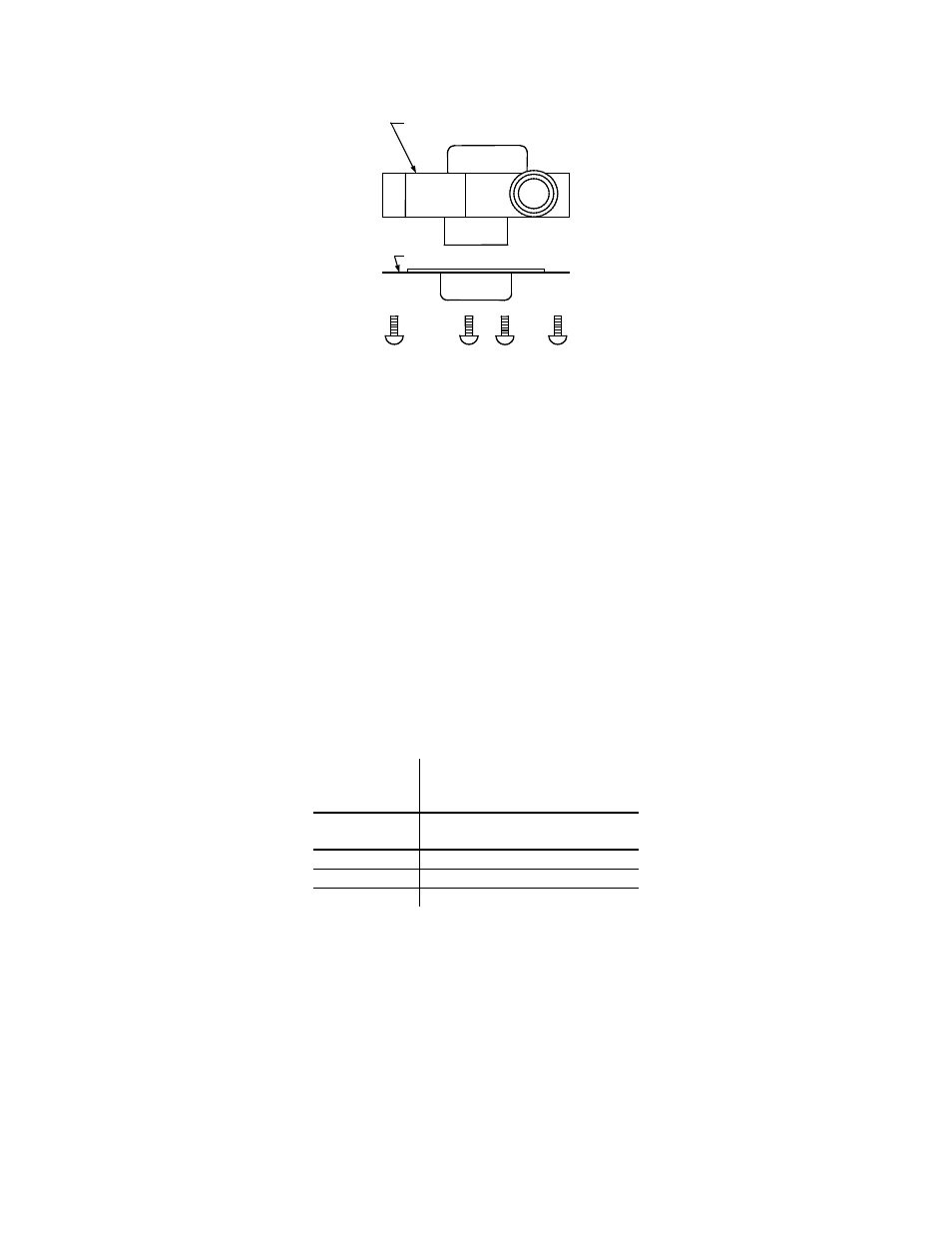
IMPELLER HOUSING
COVER
Figure 6.9
Impeller Housing Disassembly
19. Once the BTU transmitter has been inspected and cleaned, reassemble in the reverse order.
NOTE:
Do not attempt to adjust the Hydraulic Zero Needle Valve. This is a factory-preset item. Refer to
Figure
6.5. If setting has been tampered with or BTU transmitter is being replaced, see procedure in Section
6.12, page 6-17.
NOTE:
Compression fittings are nickel-plated and should be replaced only with nickel-plated fittings. Do not use
brass fittings
.
6.8 MANIFOLD AND EXHAUST TUBES
The presence of even trace amounts of chlorides and/or sulfur, in the combustion air and fuel sources,
can lead to the formation of deposits on the inside of the exchanger tubes, the exhaust manifold, and/or
the condensate cup. The degree of deposition is influenced by the extent of the condensing operation and
the chloride and sulfur levels that vary significantly from application to application.
The following parts will be necessary for reassembly after inspection:
GP-122537
Exhaust Manifold to
Combustion Chamber
Gasket
GP-18900
Manifold to Tubesheet
Gasket
124749
Lower Burner Gasket
124834
Upper Burner Gasket
124839
Combustion Chamber Liner
To remove the manifold for inspection:
1. Disconnect AC power and turn off the gas supply to the unit.
2. Remove the sheet metal covers from the unit.
3. Disconnect the plastic tubing from the condensate cup to drain and remove the rear covers.
4. Remove the condensate cup from under the unit and the condensate drainage tubing from the
manifold.
5. Disconnect the flame detector and ignition cable wires from the flame detector and ignitor contactor.
Remove the flame detector and ignitor as per paragraphs 6.2, and 6.3.