AERCO KC1000 Low NOx Boiler July 2011 User Manual
Kc series gas fired low nox boiler system
REVISED JULY 7, 2011
GF-109LN
OMM-0019_0B
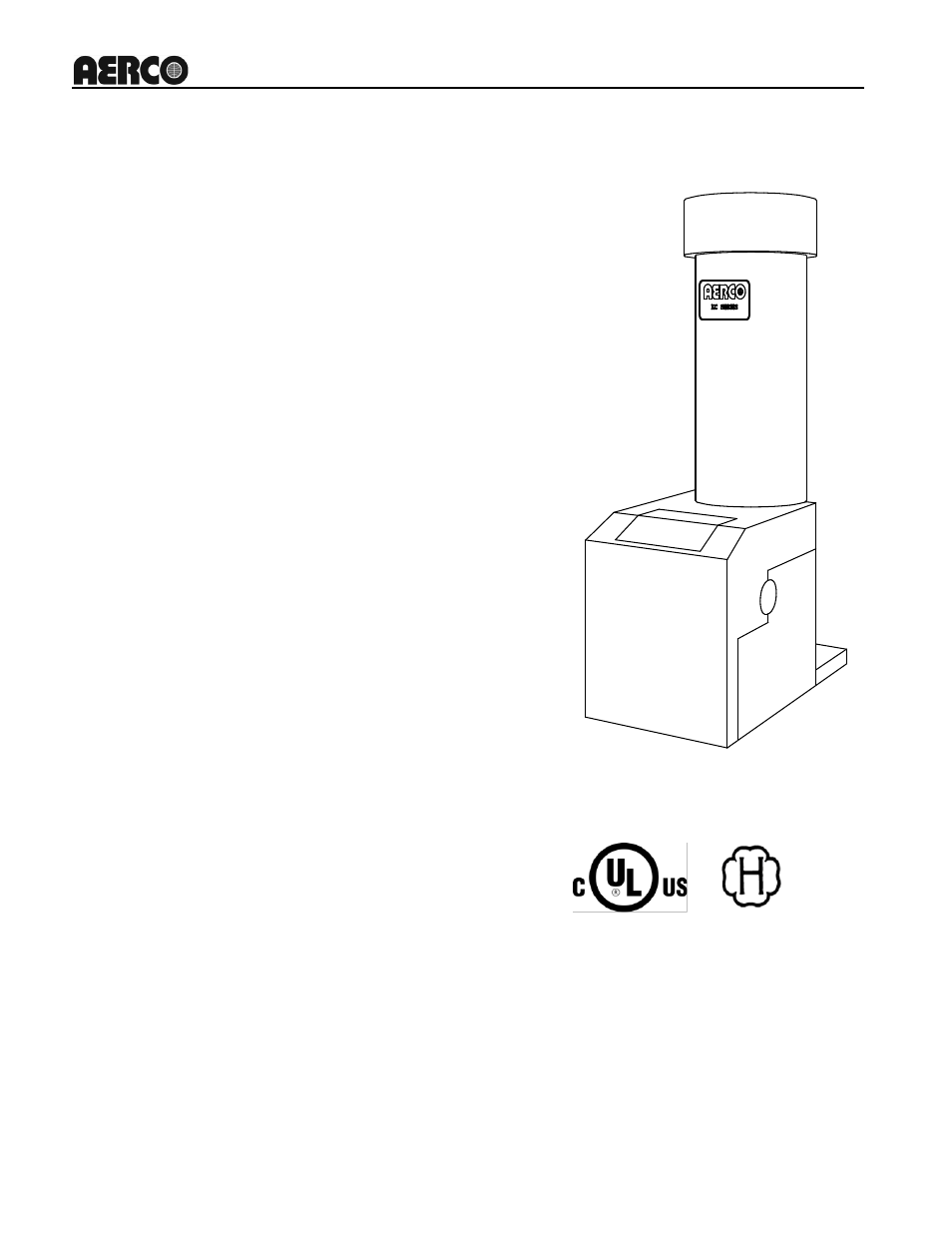
KC Series Gas-Fired Low NOx Boiler
USER MANUAL
Applicable to Serial Numbers G-11-0695 and above
KC Series
Gas Fired
Low NOx
Boiler System
Natural Gas and Propane Fired,
Condensing and Forced Draft Hot Water
Boiler
970,000 BTU/HR Input (Natural Gas)
1,000,000 BTU/HR Input (Propane)
Patent No. 4,852,524
Table of contents
Document Outline
- OMM-0019_0B_GF-109LN_KCLN_G-11-0695 and Up_01_Cover_7-7-11
- OMM-0019_0B_GF-109LN_KCLN_G-11-0695 and Up_02_TOC_6-22-10
- FOREWARD A
- SECTION 1 – SAFETY PRECAUTIONS 1-1
- SECTION 2 – INSTALLATION PROCEDURES 2-1
- SECTION 3 – CONTROL PANEL OPERATING PROCEDURES 3-1
- SECTION 4 – INITIAL START-UP 4-1
- Section 5 – MODE OF OPERATION 5-1
- SECTION 6 – SAFETY DEVICE TESTING PROCEDURES 6-1
- SECTION 7 – MAINTENANCE 7-1
- SECTION 8 – TROUBLESHOOTING 8-1
- SECTION 9 – RS232 COMMUNICATION 9-1
- APPENDICES
- WARRANTIES W-1
- OMM-0019_0B_GF-109LN_KCLN_G-11-0695 and Up_03_Fwd_10-05-09
- OMM-0019_0B_GF-109LN_KCLN_G-11-0695 and Up_04_CH1_07-07-11
- OMM-0019_0B_GF-109LN_KCLN_G-11-0695 and Up_05_CH2_7-7-11
- Figure 2.1. Boiler Clearances
- Figure 2.2
- Figure 2.3
- Figure 2.4
- Figure 2.5a
- Figure 2.5b
- Figure 2.6
- Figure 2.7
- Figure 2.8
- Figure 2.10
- 2.6.1 CONSTANT SETPOINT MODE
- 2.6.3 BOILER MANAGEMENT SYSTEM (BMS) MODE
- 2.6.4 REMOTE SETPOINT and DIRECT DRIVE MODES
- 2.6.5 COMBINATION MODE
- 2.7 I/O BOX CONNECTIONS
- 2.8 AUXILIARY RELAY CONTACTS
- OMM-0019_0B_GF-109LN_KCLN_G-11-0695 and Up_06_Ch3_4-19-11
- OMM-0019_0B_GF-109LN_KCLN_G-11-0695 and Up_07_Ch4_6-21-10-NEW
- OMM-0019_0B_GF-109LN_KCLN_G-11-0695 and Up_08_CH5_6-16-10
- OMM-0019_0B_GF-109LN_KCLN_G-11-0695 and Up_09_Ch6_3-25-11
- OMM-0019_0B_GF-109LN_KCLN_G-11-0695 and Up_10_Ch7_1-7-10-bb
- OMM-0019_0B_GF-109LN_KCLN_G-11-0695 and Up_11_Ch8_09-29-10
- 8.1 INTRODUCTION
- 1. Measure the actual exhaust temperature and continuity of the exhaust sensor. If the exhaust temperature is less than 475 o F and the exhaust sensor shows continuity replace the sensor.
- 2. If exhaust temperature is greater than 500 o F, check combustion calibration. Calibrate or repair as necessary.
- 2. If there are two external wires on these terminals check any Energy Management system to see if they have the units disabled (a jumper may be temporarily installed to see if the interlock circuit is functioning).
- 3. Check that proving switch for any device hooked to the interlock circuit is closing and that the device is operational.
- OMM-0019_0B_GF-109LN_KCLN_G-11-0695 and Up_12_CH9_6-16-10
- OMM-0019_0B_GF-109LN_KCLN_G-11-0695 and Up_13_App-A_3-25-11
- OMM-0019_0B_GF-109LN_KCLN_G-11-0695 and Up_14_App-B_10-01-09
- OMM-0019_0B_GF-109LN_KCLN_G-11-0695 and Up_15_App-C
- OMM-0019_0B_GF-109LN_KCLN_G-11-0695 and Up_16_App-D
- OMM-0019_0B_GF-109LN_KCLN_G-11-0695 and Up_17_App-E_3-25-11
- OMM-0019_0B_GF-109LN_KCLN_G-11-0695 and Up_18_App-F_6-16-10
- OMM-0019_0B_GF-109LN_KCLN_G-11-0695 and Up_19_App-G_10-01-09
- OMM-0019_0B_GF-109LN_KCLN_G-11-0695 and Up_20_App-H_07-01-06
- OMM-0019_0B_GF-109LN_KCLN_G-11-0695 and Up_21_App-I_12-27-08
- OMM-0019_0B_GF-109LN_KCLN_G-11-0695 and Up_22_APP-J
- OMM-0019_0B_GF-109LN_KCLN_G-11-0695 and Up_23_APP-K
- Blank Page
- Blank Page
- Blank Page
- Blank Page
- Blank Page
- Blank Page
- Blank Page
- Blank Page