Vermont Casting DVR28IN User Manual
Page 26
26
20012301
Vermont Castings DVR28 Direct Vent Gas Fireplace
Troubleshooting AF4000 Valve
(continued)
Pilot will not light/stay lit
•
Verify the gas supply is turned on.
•
Verify the receiver is receiving the signal from the transmitter by listening for a
beep from the receiver when ON is pressed on the transmitter. If you do not hear
a beep, ensure the module has learned the transmitter (see above).
•
Ensure the orange lead from the pilot assembly igniter is securely connected to
the terminal labeled “I” and the white lead from the flame rectification sensor is
securely connected to the terminal labeled “S” on the control module. (Fig. 37)
•
Make sure the orange and white leads from the module are securely connected to
the terminals labeled “PILOT” on the valve body. (Fig. 42)
•
Ensure the black GROUND wire is securely connected to an appropriate metal
portion of the valve or pilot assembly. A proper ground is essential to spark
igniter operation.
•
Make certain the pilot flame is in contact with the flame rectification sensor on the
pilot assembly. This valve is equipped with a pilot flame adjustment screw. (Fig.
42) If the pilot flame is too small it will not contact the flame rectification sensor
and will not complete the safety circuit.
������
�����������������
����
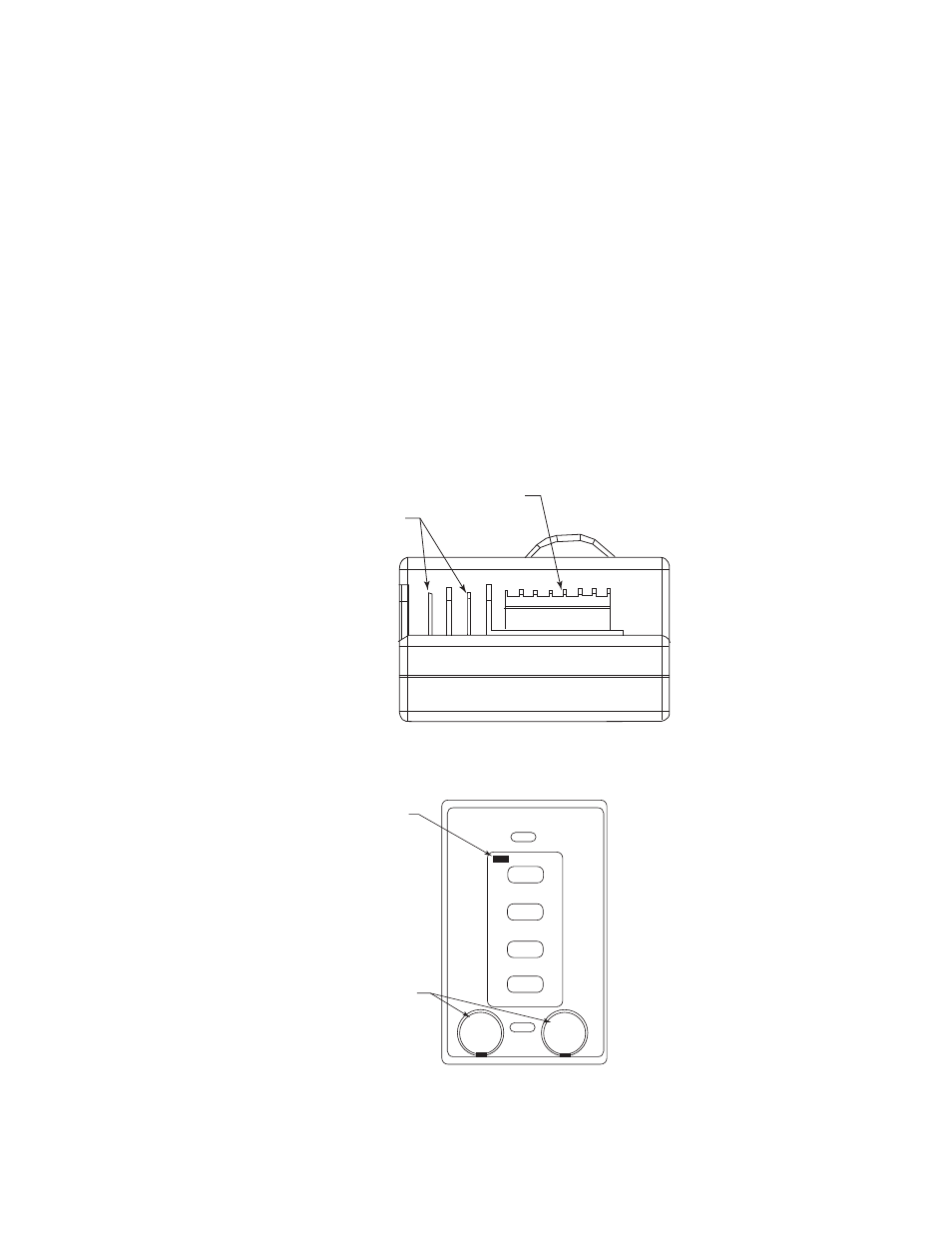
6 Volt DC Adapter
Power Connection
8 Pin IPI
Connection
FP1764
Figure 39: AF4000 MOD Module End
+
Plus
Side
+
Plus
Side
FP1766
wall transmitter face
2/07
30 MIN
60 MIN
120 MIN
OFF
Indicator Light
Insert batteries into
holder and snap into
holder.
(Plus sides face front)
Figure 40: Wall Transmitter Face
FP1766