Troubleshooting – Vermont Casting DVR28IN User Manual
Page 25
20012301
25
Vermont Castings DVR28 Direct Vent Gas Fireplace
Troubleshooting
AF4000 Valve
If erratic system behavior is observed that cannot be resolved by the methods outlined below, ensure that there is
not a transmitter with batteries installed that may be interfering. If a transmitter is packed with batteries installed, its
buttons may be depressed sending a constant signal which can interfere with the transmission of desired signals. A
transmitter with new batteries can have a range of over 100’ (30.4 m).
Module will not learn trans-
mitter
•
Ensure the REMOTE/OFF switch on the side of the module (Fig. 37) is set to RE-
MOTE.
•
Make sure the batteries in both the transmitter and receiver are installed in the
proper direction (Fig. 41) and are not drained. Individual battery voltage should be
no less than 1.4V for AA and AAA batteries, 2.8V for button cells, and 9,0V for 12V
batteries.
•
Verify the transmitter indicates a signal is being sent. With thermostat transmitters,
the LCD display should indicate ON or OFF depending on which button is being
pressed. The LED indicator should illuminate on wall transmitters and on/off hand-
held transmitters. (Fig. 43) Buttons should be pressed and held for 1 to 2 seconds
to ensure a complete signal is sent.
•
Make sure the transmitter is within the 20’ (6 m) operational range of the receiver.
•
Ensure the 4-pin lead-set is securely connected from the battery pack to the
control module’s AUX connection. (Figs. 38, 41) If the A/C power adapter is used,
make sure the leads from the adapter are securely connected to the POWER
terminals on the control module. (Fig. 39)
•
Press and hold the LEARN button on the module (Fig. 38) for approximately 10
seconds to clear the memory (you should hear a series of beeps from the re-
ceiver). Then press and release the learn button (you should hear a single beep
from the receiver), immediately press either the ON or OFF button on the transmit-
ter (you should hear a series of beeps indicating the transmitter code has been
learned).
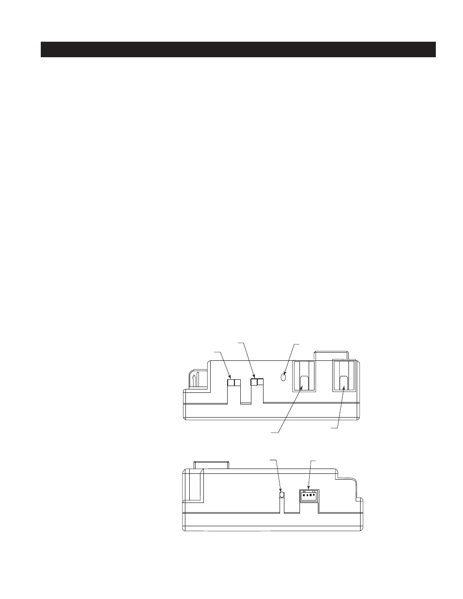
������
������������������������
����
Continuous PIlot
Off/On Switch
Remote/Off
Switch
Adjustment
“S” Pilot Connection
“I” Pilot
Connection
FP1762
Figure 37: AF4000
MOD Module Right
Side
������
�����������������������
����
Learn Button
AUX Connection
FP1763
Figure 38: AF4000
MOD Module Left Side