Dampertech_2010 370, Operation – AERCO Belimo AMX24-MFT Actuator User Manual
Page 9
800-543-9038 USA
866-805-7089 CANADA
203-791-8396 LATIN AMERICA
370
Manual Override Button
10 VDC
10 VDC
2 VDC
Direction of Rotation Switch
65°
Operation
Mechanical Features
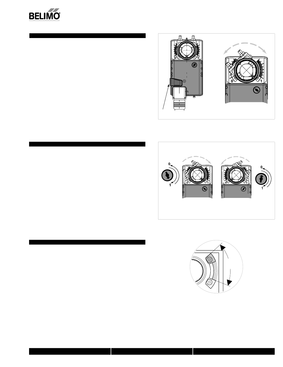
Manual Override
The Belimo non-spring return actuators have a black, “manual override button”
located on the top of the housing. Press this button and the gear train is
disengaged so the damper shaft can be moved manually. Release the button and
the gear train is re-engaged.
Use the manual override to test the installation without power. For tight shut-off the
damper should close with 5° of actuator stroke left.
Direction of Rotation Switch
Non-spring return actuators have a reversing switch on the cover. Switch position
indicates start point. For the non-spring return, with the switch in position 1, the
actuator rotates clockwise with an decrease in voltage or current. With the switch
in position 0, the actuator rotates counterclockwise with an decrease in voltage or
current.
The non-spring return rotates clockwise when the switch is in the 1 position and
power is applied to wire #2. When power is applied to wire #3 the actuator rotates
counter clockwise. Rotating the switch to 0 reverses the control logic.
During checkout, the switch position can be temporarily reversed and the actuator
will reverse its direction. This allows the technician a fast and easy way to check
the actuator operation without having to switch wires or change settings on the
thermostat. When the check-out is complete, make sure the switch is placed back
to its original position.
Mechanical Angle of Rotation Limiting
The adjustable stops are needed when there is no damper stop or if you want the
damper to stop rotating before it reaches its stops. The non-spring return actuators
can be indefinitely stalled in any position without harm.
1. Loosen the two end stops with a No. 2 Phillips head screwdriver being careful
not to unscrew the captive nut under the slot.
2. Move the stops (in 2.5° steps) to the desired position and re-tighten the screws.
M40024 - 05/10 - Sub
ject to chan
g
e.
© Belimo
Aircontrols
(USA
), Inc.