2 motherboard layout, 5cm(4.53in), 5cm(6.5i n) – faytech Industrial Motherboard Series User Manual
Page 10
11
12
13
14
9
SATA_PWR1
DDR3 DIMM_A1
DC_PWR
EATX_PWR1
CHA_FAN1
Place this side towards
the rear of the chassis
19
18
17 16
COM3
COM4
J1
15
2-2
faytech Motherboard
2.2
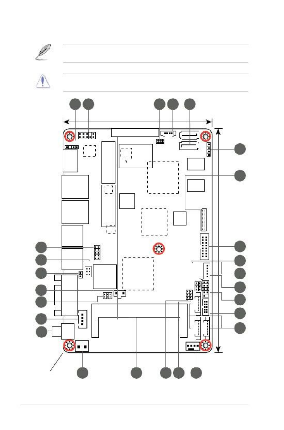
Motherboard layout
NOTE: Place five screws into the holes indicated by circles to secure the
motherboard to the chassis.
CAUTION! Do not overtighten the screws! Doing so can damage the
motherboard.
1
2
PCIeX1
3
11.5cm(4.53in)
AAFP1
4
5
AMP_CON1
SPEAKER
SPDIF_OUT1
HDMI1
ALC
887
MINI_CARD1
SPI1
SIM1
ICS
9VRS4339AL
SATA3G_2
SATA3G_1
ISD72
D9MGG
6
7
AMD
®
HD7410M
LAN1
RTL
8111F
AMD
®
GPU (optional)
PEX8605
ISD72
D9MGG
MINI_CARD2
PLX
LAN2
USB2
RTL
8111F
Intel
®
NM10
R560
010S LVDS1
16.5cm(6.5i
n)
DIO1
COM2
COM1
J2
N2600
BATTERY
LVDS_VDD_SEL1CLRTC
1
24
23
22
21
20
Super
I/O
Intel
®
F_PANEL1
INV1
KBMS1
LCD_POWER_SEL1L_B
RIGHTNESS1
25
USB3
USB1
26
VGA
8
10