System a - 100, A-196, User examples – Doepfer A-196 PLL User Manual
Page 7: Doepfer, Frequency multiplication, Grafic vco
doepfer
System A - 100
PLL
A-196
7
6. User examples
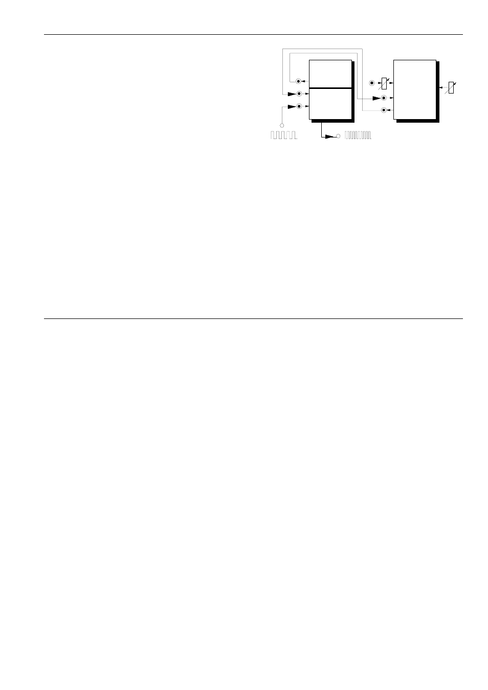
Frequency Multiplication
A very important application of the A-196 is frequency
multiplication. For this the output of the internal VCO
is connected to the input of an external frequency
divider (e.g. the VC frequency divider A-163 or the
A-160). The output of the divider is connected to input
§
of the phase comparator (see fig. 2). By this the
internal VCO oscillates at a multiple of the frequency of
the external signal. The multiple is defined by the
setting of the frequency divider. For this application
PC2 is recommended as it does not lock at harmonics.
Example: Setting the A-163 to a dividing factor 5
causes the fivefold frequency at the VCO output of the
A-196 compared to the frequency of the external signal
fed into input 2 of the PC (multiple A-180 at the VCO
out of A-196 required, not shown in fig.2).
Using the A-163 consequently leads to a voltage con-
trolled frequency multiplication. Modulating the A-163
dividing factor passes through several pseudo-
harmonics, "pseudo" as the waveform of the A-196
VCO is rectangle in contrast to real sine shaped har-
monics.
Fig. 2: Frequency multiplication with A-163
Grafic VCO
Frequency multiplication can be used to generate the
clock signal for a graphic VCO. For this e.g. the
A-155 can be used even though it is equipped with
rotary controls instead of faders as usual for graphic
VCOs.
For this the Clock input of the A-155 is connected to
the A-196 VCO output. The frequency of an external
VCO (e.g. A-110) is multiplied with the A-196 by 8 - as
the A-155 has 8 steps. The waveforms of the audio
signals that appear at the two Pre-Outputs of the A-155
can be adjusted with the analog controls of the A-155
like a graphic VCO. The audio frequency is identical to
the controlling "master" VCO (e.g. A-110).
Manual
CV In
A-163
VDIV
In
Out
CV
A-196
PLL
In 1
Out
VCO
PC
In 2
Out