System a - 100, A-112, Doepfer – Doepfer A-112 Sampler/Wavetable Oscillator User Manual
Page 5: Sampler, 5switch • 6 switch • 7 switch
doepfer
System A - 100
Sampler
A-112
5
5
Switch • 6 Switch • 7 Switch
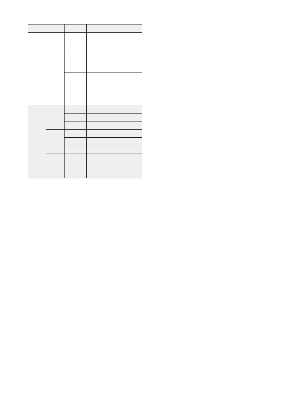
With the 3-position switches 4 to 6 the operating
mode is selected. The table on the left lists all possible
modes. The modes are described in the following
paragraphs.
In particular the gate signal (gate input § / manual
trigger 4) controls different functions in the respective
operating modes.
H
Please note that in some modes it is not
sufficient to change the switches position to
exit the mode. In the following description of
the modes you will find detailed information
on how to exit a selected mode.
5
5
5
5
6
6
6
6
7
7
7
7
Function
Loop
not implemented
Dmp
Norm
Dump a sample
Wav
Dump a wave
Loop
Play a loop
S1, S2
Play
Norm
Play a sample
Wav
Play a wave
Loop
Record a loop
Rec
Norm
Record a sample
Wav
Record a wave
Len
Input sample length required
Pit
Norm
Pitch Shift
Frz.
Pitch Shift with "Freeze"
Len
Input sample length required
Eff
Del
Norm
Delay
Frz.
Delay with "Freeze"
Len
Input sample length required
Rev
Norm
Reverse Delay
Frz.
Reverse Delay with "Freeze"
- DIY Synth do-it-yourself analog synthesizer (24 pages)
- MKE Universal Midi Keyboard Electronics Kit (17 pages)
- CTM64 Contact to Midi Interface (main board) (20 pages)
- CTM64 Relay Board (8 pages)
- MTC64 Midi to Gate Interface (main board) (16 pages)
- MTC64 Relay Board (8 pages)
- MTC64 Output Board (transistor driver board) (4 pages)
- MTC64 Power Board (8 pages)
- Pocket Electronic (32 pages)
- Dial Electronic (12 pages)
- Wheel Electronic (16 pages)
- USB64 Universal Midi and USB Controller Electronics Kit (20 pages)
- MBP25 Midi Bass Pedal Electronics Kit (16 pages)
- MTV16 Midi-to-Voltage Interface with 16 Analog Voltage Outputs (8 pages)
- A-100 (8 pages)
- A-100AD5 +5V low cost adapter (46 pages)
- A-100(~ 40 MB) (744 pages)
- A-100CGK CV/Gate keyboard (12 pages)
- A-101-1 Vactrol Steiner Filter (6 pages)
- A-101-2 Vactrol Lowpass Gate (6 pages)
- A-101-3 Vactrol Modular Phase Filter (10 pages)
- A-101-9 Universal Vactrol Module (14 pages)
- A-102 Diode Low Pass (6 pages)
- A-104 four-fold Trautonium Formant Filter (6 pages)
- A-105 24dB SSM Low Pass (8 pages)
- A-106-1 Xtreme Lowpass/Highpass Filter (12 pages)
- A-107 Multitype Morphing Filter (18 pages)
- A-108 6/12/24/48 Formant Filter (10 pages)
- A-109 Voltage Controlled Audio Signal Processor (10 pages)
- A-110 Standard VCO (12 pages)
- A-111-1 High End VCO (14 pages)
- A-111-5 Synthesizer Voice (22 pages)
- A-113 Subharmonic Oscillator (14 pages)
- A-114 Dual Ringmodulator (6 pages)
- A-115 Audio Divider (6 pages)
- A-116 VC Waveform Processor (6 pages)
- A-117 Digital Noise / 808 Source (8 pages)
- A-118 Noise/Random (6 pages)
- A-119 External Input/Envelope Follower (8 pages)
- A-120 24dB Low Pass 1 (8 pages)
- A-121 12dB Multimode VCF (10 pages)
- A-123 24dB High Pass (no longer available) (8 pages)
- A-124 Wasp Filter (8 pages)
- A-125 VC Phaser (8 pages)