System a - 100, A-112, Doepfer – Doepfer A-112 Sampler/Wavetable Oscillator User Manual
Page 11: Sampler
doepfer
System A - 100
Sampler
A-112
11
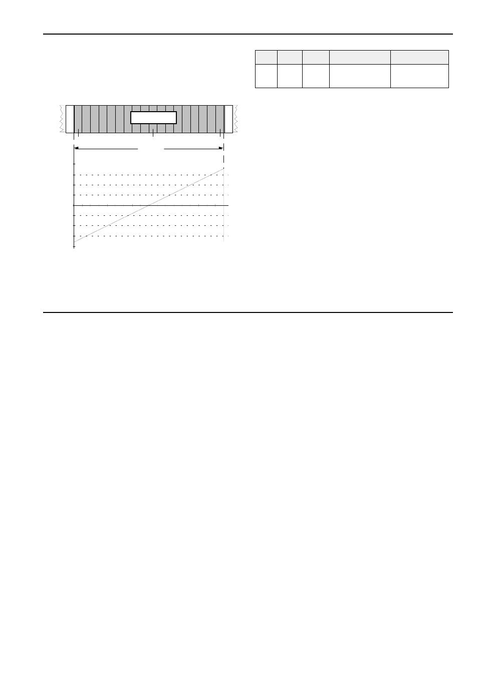
i.e. the next wavetable and the next sampling fre-
quency are determined. This continues until the gate
goes low.
When a dynamic voltage -2.5...+2.5V is used as the
wavetable control voltage (e.g. ADSR output connec-
ted to audio/wave input !) wavetable are swept.
fig. 4:
wavetable selection with CV voltage applied
to audio/wave input
• Normal dump mode
In this mode a sample (bank 1 or 2) can be transferred
as a MIDI system exclusive string (SysEx Dump) via
MIDI out &. You can then record this string with a MIDI
computer sequencer or download it using a MIDI dump
program for storage on hard disk or any other storage
device. The sampling frequency is also transferred
within the string.
It is also possible to receive a sample dump via MIDI
input %. The dump is written to the memory bank
selected (S1 or S2).
Gate = low:
In this state (LED 3 off) MIDI input % is scanned. As
soon as an incoming sample dump is detected LED
3
turns on and the dump data is written into the
memory bank selected.
If a sample dump request is received via MIDI IN the
sample memory is transferred via MIDI OUT as a
SysEx string. LED 3 turns on as well. Refer to the
description of MIDI input and output in chapter 5.
-0,40
-0,30
-0,20
-0,10
0,00
0,10
0,20
0,30
0,40
Audio In
127
118
135
Speicherbank
Loop
memory bank
5
5
5
5
6
6
6
6
7
7
7
7
Audio / Wave-CV In
Tune / CV
S1,
S2
Dmp Norm