Doepfer – Doepfer A-101-9 Universal Vactrol Module User Manual
Page 3
DOEPFER
DOEPFER
DOEPFER
DOEPFER
System A-100
Universal Vactrol Module A-101-9
3
Normally the vactrol is connected in parallel to the
resistor/potentiometer that controls the parameter in
question and the potentiometer is set to it's maximum value
(e.g. 1 M
Ω). The dark resistance of the vactrol is several
M
Ω and consequently has no or little effect to the overall
value. As the brightness inside the vactrol increases the
LRD resistance becomes smaller and has the same effect
as operating the potentiometer. The existing potentiometer
can also be used to determine the upper value of the
parameter in question if it is not set to it's maximum value.
Typical example: a 1 M
Ω potentiometer is used to control
the decay of an envelope generator by discharging a
capacitor to GND. The vactrol is connected in parallel to the
decay potentiometer. The setting of the potentiometer
defines the maximum decay time as the vactrol can only
reduce the total resistance and consequently reduce the
decay time.
Even a trimming potentiometer or a fixed resistor can be
replaced or switched in parallel to one of the vactrol outputs
of the A-101-9. If this makes sense depends upon the circuit
in question and can be used for circuit bending applications.
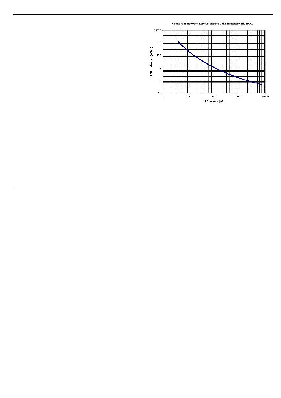
In order to obtain a reasonable control scale the A-101-9
uses a logarithmic current source for the vactrol LEDs. With
a linear relationship between the applied control voltage and
the LED current the overall resolution would be very
unsuitable. Fig. 2 shows the relation between LED current
and LDR resistance of a vactrol (both scales of the graph
are logarithmic).
Fig. 2: Relation between LED current and LDR resistance of
a vactrol
Remark:
The A-101-9 cannot be used (or only with limitations) to
replace a three-terminal-potentiometer (voltage divider) as
the vactrol is a two terminal element only. Under certain
conditions a three-terminal-potentiometer can be replaced
by a fixed resistor and the vactrol connected in series. But
this is possible only if the circuit is not sensitive to the
overall resistance (vactrol+fixed resistor) as this changes
while the vactrol changes it's value. One has to look at the
schematics if this is true or try it out.