Doepfer MTC64 Midi to Gate Interface (main board) User Manual
Page 14
Page 14
MTC64 V2 User’s Guide
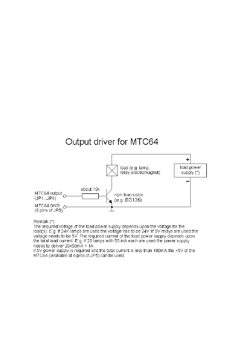
Output Driver Circuit
The MTC64 outputs are able to drive only about max. 5 mA in the "high" state (+5V) and
about max. 10 mA in the "low" state (0V). If one wants to drive higher loads (e.g. lamps,
relays, electromagnets, electromagnetic valves or similiar) an additional driver for each
MTC64 output is required. Each MTC64 output is connected to the base of a power transistor
(e.g. BD135) via a resistor (about 10 kOhm). The emitter of the transistor is connected to
GND. The load (i.e. the lamp, relay and so on) is connected between the collector of the
transistor and the positive power supply for the load(s). The voltage of the power supply has
to agree with the voltage of the load(s). E.g. if 24V relays are used the power supply needs
to be 24V. The current of the power supply is the sum of the currents of all loads. E.g. if 64
relays with 20mA each are used a power supply with 64 x 20mA = 1280mA = 1.3 A is
required. In this example a power supply with 24V/1.3A would be necessary.
The auxiliary +5V power supply of the MTC64 (4 pins of JP5) can be used only if +5V
voltage and not more than 100mA are required. In other cases an external power supply is
necessary.
As suitable driver board with 16 drivers is planned for end of 2001. Please ask is you are
interested.