Z force – Cub Cadet Z-Force Series User Manual
Page 28
Z Force
24
12.3. Lift the control housing over the brake lever, if
working on the left side control console, and set
it out of the way.
NOTE: The throttle cable will still be attached to
the left side control console. Be careful no tot
damage it.
NOTE: Disconnect any electrical components
that inhibit the movement of the control console.
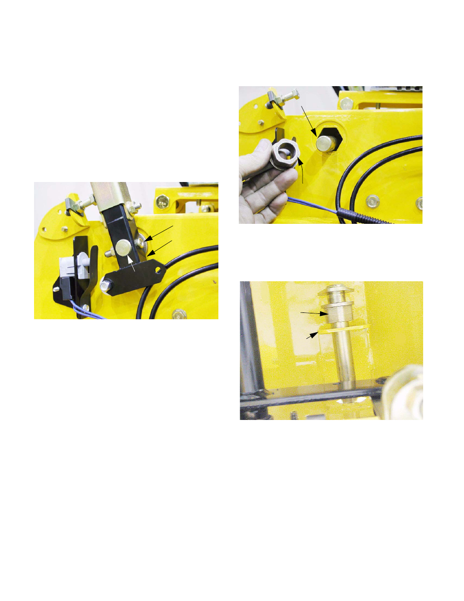
12.4. Remove the nut and socket head cap screw that
hold the pivot bracket to the steering input shaft
using a 1/4” Allen wrench and a 1/2” wrench.
See Figure 12.4.
12.5. Slide the lap bar and pivot bracket assembly off
of the steering input shaft.
NOTE: If the socket head cap screw has left a
burr on the steering input shaft, de-burr the shaft
before attempting to remove it.
12.6. Push the steering input shaft into the control
housing far enough to allow the removal of the
outside bushing.
12.7. Remove the outer bushing, and push the inner
bushing out of the hexagonal hole that it resides
in. See Figure 12.7.
12.8. Maneuver the steering input shaft into a vertical
position so that it and the inner bushing can be
removed. See Figure 12.8.
12.9. Replace any parts that are worn or damaged,
and install the steering input shaft by reversing
the removal process.
Figure 12.4
Socket head
cap screw
Pivot bracket
Steering input
shaft
Figure 12.7
Outer
bushing
Steering input shaft
Figure 12.8
Inner hex bushing
Inner bracket