Z force – Cub Cadet Z-Force Series User Manual
Page 22
Z Force
18
10.15.The PTO switch is located just behind the key
switch.
•
Terminal A (Common) to G: Orange wire with
white trace leads to parking brake switch from
terminal A. The N.O. contacts in the parking
brake close when the parking brake is applied,
completing the path to trigger the solenoid. The
orange wire with black trace provides power to
terminal G when the N.O. contacts of both neu-
tral switches are closed by moving the lap bars
into the “start” position. Starter inhibit circuit.
•
Terminal B (common) to terminal E: Yellow wire
with black trace leads from terminal B to terminal
A on relay #3, where it completes a path to
ground if the relay is energized by the seat
switch. Terminal E has 2 yellow wires with white
traces. Each one leads to the N.C. contacts on
one of the 2 neutral switches. If the PTO switch
is turned on, and the seat is empty, a ground
path is completed to the magneto, turning off the
engine.
•
Terminal C (common) to terminal F: A red wire
provides power to terminal C from the L terminal
on the key switch. When the PTO switch is in
the ON position, contacts are closed to terminal
F. 2 blue wires on terminal F provide power to
the PTO clutch via the 2 reverse switches.
10.16. The starter solenoid is located near the right
rear corner of the control console.
See Figure 10.16.
10.17.The voltage regulator / rectifier is located near
the left front corner of the engine, adjacent to the
starter motor. See Figure 10.17.
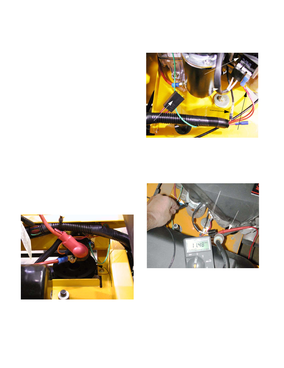
10.18.To test stator out-put, disconnect the plug from
the regulator / rectifier. Start the engine, and run
it at full throttle. Checking A.C. voltage at each
white wire should yield a reading of roughly 11
volts. See Figure 10.18.
Figure 10.16
STARTER SOLENOID
Figure 10.17
Magneto ground
Fuse (20A)
Regulated out-put
from stato
r
A.C. out-p
ut
Regulator/
rectifier
Figure 10.18
Stator out-put leads
Red probe
from DVOM
Black probe from
DVOM to ground