Z force – Cub Cadet Z-Force Series User Manual
Page 15
Z Force
11
8.7.
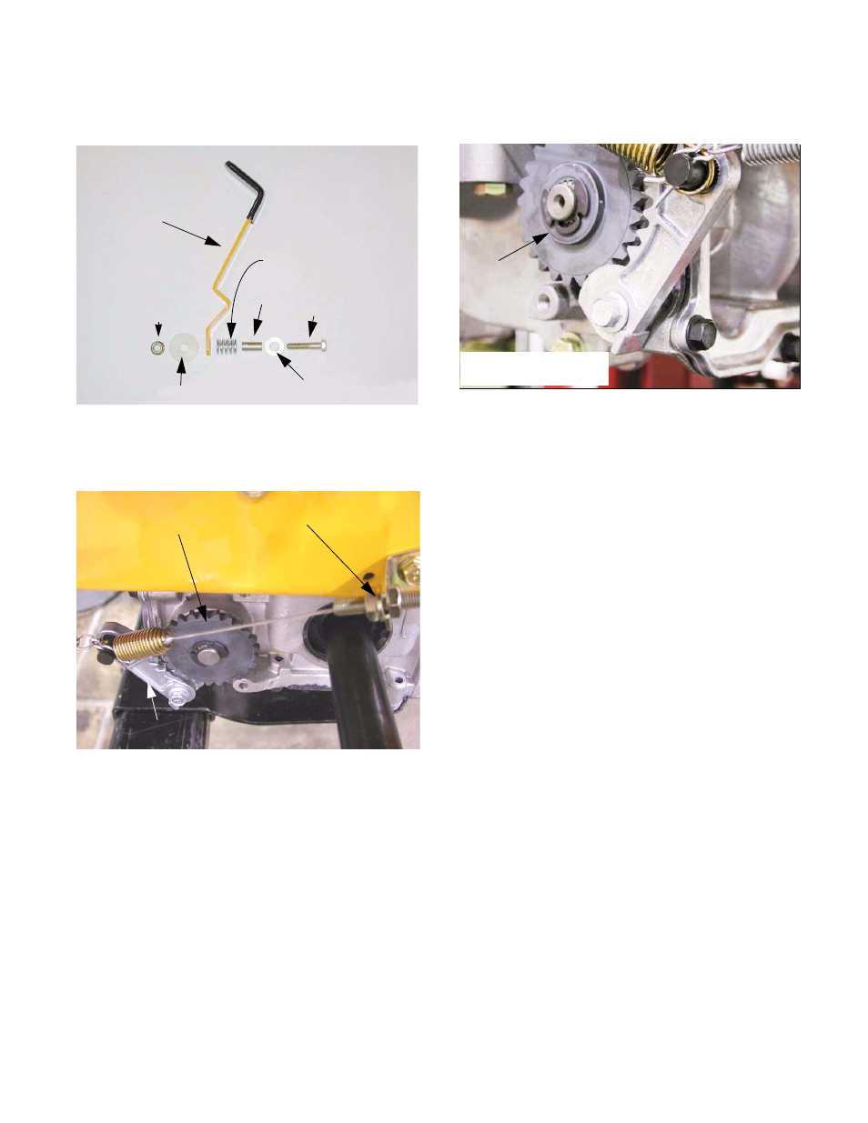
Check the brake lever mounting hardware.
See Figure 8.7.
8.8.
Prior to adjustment, check the brake pawls and
rotors. See Figure 8.8.
•
The teeth on the pawls and rotors should not be
worn, chipped or rounded.
•
Both ends of the brake shaft on each transmis-
sion are splined. The brakes are mounted to the
outside of each transmission.
•
The right side brake rotor fits on the brake shaft
with the shoulder facing the transmission.
•
The shoulder on the pawl should face in the
same direction as the shoulder on the rotor that
it engages. The pawl should not bind on the
shoulder of the bolt that it pivots on.
Figure 8.7
Nut
Friction washer
Parking brake lever
Spacer
Flat washer
Capscrew
Spring
Figure 8.8
Adjustment point
Brake rotor
Brake pawl
8.9.
Prior to adjustment, check the brake pawls and
rotors. See Figure 8.9.
•
The teeth on the pawls and rotors should not be
worn, chipped or rounded.
•
Both ends of the brake shaft on each transmis-
sion are splined. The brakes are mounted to the
outside of each transmission.
•
The left side brake rotor fits on the brake shaft
with the shoulder facing the wheel.
•
The shoulder on the pawl should face in the
same direction as the shoulder on the rotor that
it engages. The pawl should not bind on the bolt
that it pivots on.
8.10. Pull out both hydro. pump rods to disengage the
hydraulic brakes.
8.11. Install the left side control console.
8.12. Move the parking brake lever to the ON position.
8.13. Check for full tooth engagement between each
brake pawl and rotor. If they are not fully
engaged, move the corresponding rear hub
slightly to align the teeth.
Figure 8.9
Shoulder
Shoulder out.
Right side brake rotor: