Z force – Cub Cadet Z-Force Series User Manual
Page 10
Z Force
6
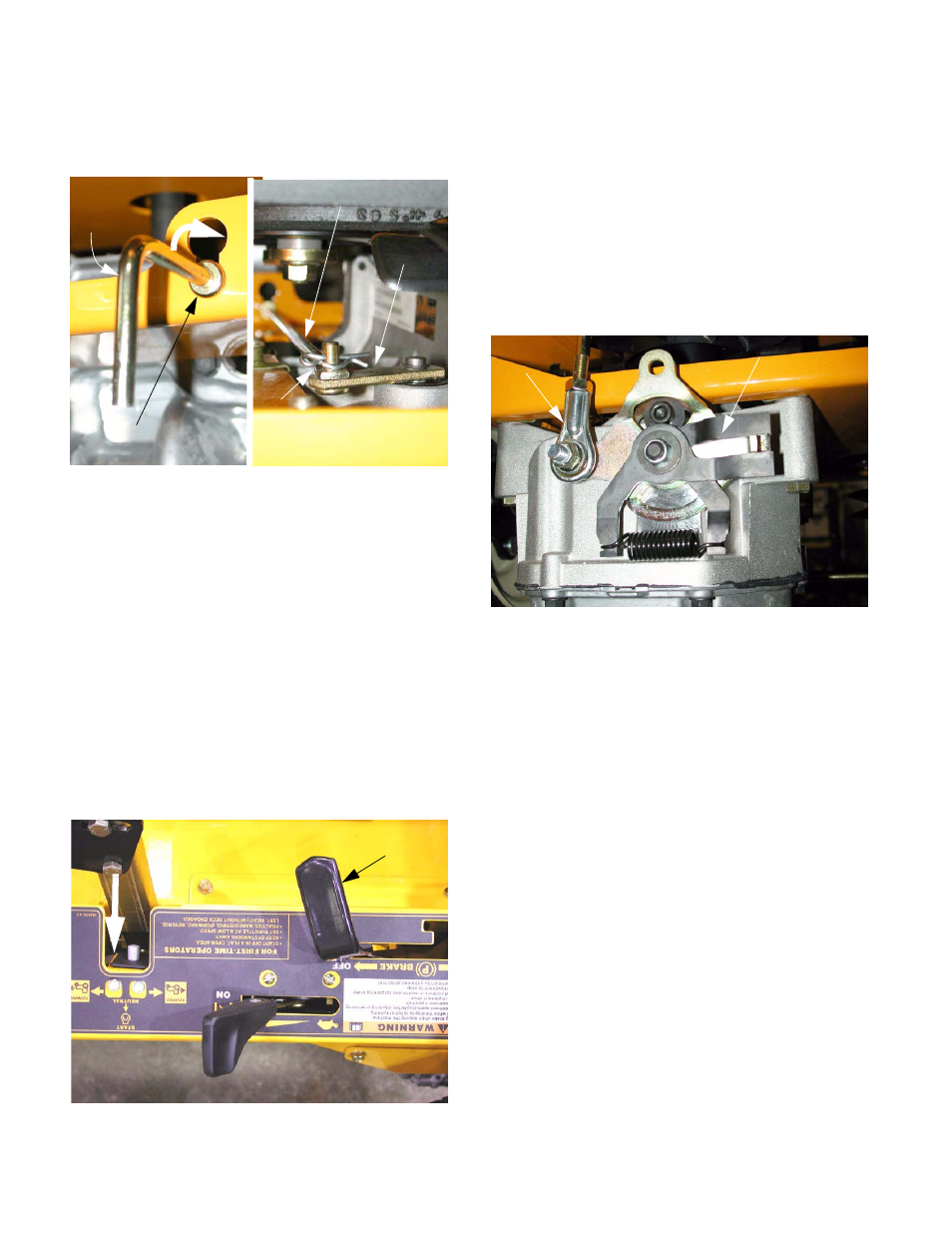
6.5.
Check the IHT (Integrated Hydrostatic transmis-
sion) release the levers to be sure the transmis-
sions are fully engaged. See Figure 6.5.
6.6.
Check steering linkage for wear and damage.
i.e.; loose ball joint ends, worn bellcrank bush-
ings, and loose or bent hardware.
6.7.
Replace any worn or damaged components
before attempting to make a tracking adjust-
ment.
6.8.
After the preliminary items have been covered,
check the neutral adjustment.
6.9.
Raise rear wheels off ground and support the Z-
Force by the frame.
6.10. Start the engine and release parking brake, do
not move the lap bars from the start position.
Neither the rear wheels nor the brake rotors
should move. See Figure 6.10.
6.11. Turn the engine off and remove the key from the
switch.
6.12. If there is wheel movement in neutral, discon-
nect the control linkage from the transmission
that is driving that wheel.
NOTE: If both wheels “creep” then both control
linkages need to be disconnected.
6.13. Using two 1/2” wrenches, remove the Nylock nut
holding steering link rod end to the return-to-
neutral mechanism. See Figure 6.13.
6.14. With the steering link rod disconnected, start the
engine, release the parking brake, and check for
wheel and brake rotor movement.
6.15. If “creep” has been eliminated by disconnecting
the linkage, then only the linkage must be
adjusted to eliminate the “creep”. If “creep” still
exists, then the return-to-neutral mechanism on
the transmission must be adjusted.
Figure 6.5
Release rod for right
hand side IHT, seen at
rear of frame.
Released position; lift
Forward end of the same
rod, connected to lever on
right hand side IHT.
IHT release rod
IHT release
lever
and push in to engage
Figure 6.10
Parking brake
released
Leave the lap bar in the
“START” position
notch. This will hold
the lap bar in neutral.
Figure 6.13
Return-to-neutral mechanism
Steering
link rod end